
Heat exchanging device and refrigerating system

A heat exchange device and refrigeration system technology, applied in the direction of refrigerators, refrigeration components, refrigeration and liquefaction, etc., can solve the problems of adverse effects of refrigeration or heating control environment, the normal operation of intermittent refrigeration systems, and increased fluctuations of refrigeration systems, etc., to achieve Reduce the number of reverse cycle defrosting, avoid reverse cycle defrosting, and improve system efficiency

Active Publication Date: 2010-10-27
SANHUA HANGZHOU MICRO CHANNEL HEAT EXCHANGER +1
View PDF3 Cites 5 Cited by
  • Summary
  • Abstract
  • Description
  • Claims
  • Application Information

AI Technical Summary

Problems solved by technology

[0003] Traditionally, reverse cycle defrosting is used, that is, when defrosting is required, the refrigerant flows in reverse throughout the refrigeration system, the evaporator acts as a condenser, and the condenser acts as an evaporator, so the defrosting operation will interrupt the normal operation of the refrigeration system run, thereby reducing work efficiency
Moreover, due to the uneven temperature distribution on the refrigerant circulation circuit and the influence of the wind direction, the accumulation rate of the frost layer on each part of the evaporator is not equal. When the frost layer on any part of the evaporator needs to be removed, it must The evaporator needs to be defrosted. Frequent defrosting increases the fluctuation of the refrigeration system, which has an adverse effect on the refrigeration or heating control environment and will reduce the operating efficiency of the whole machine

Method used

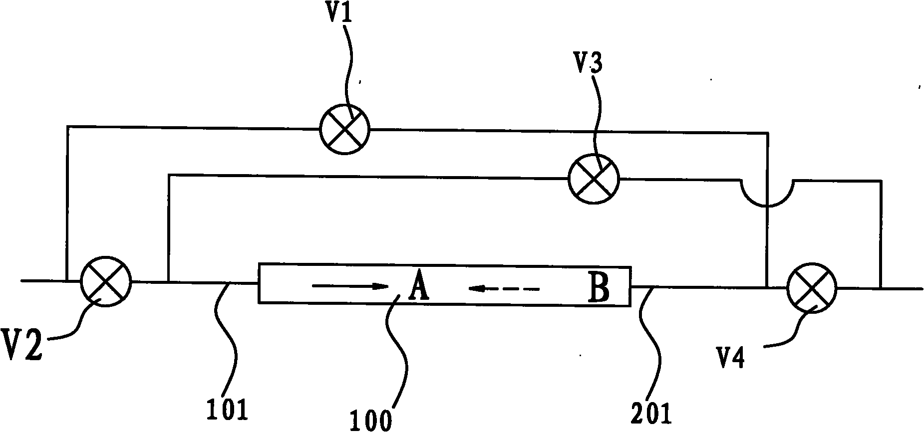
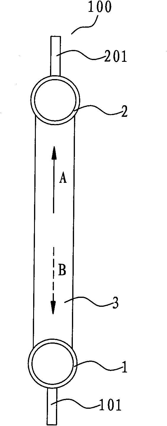
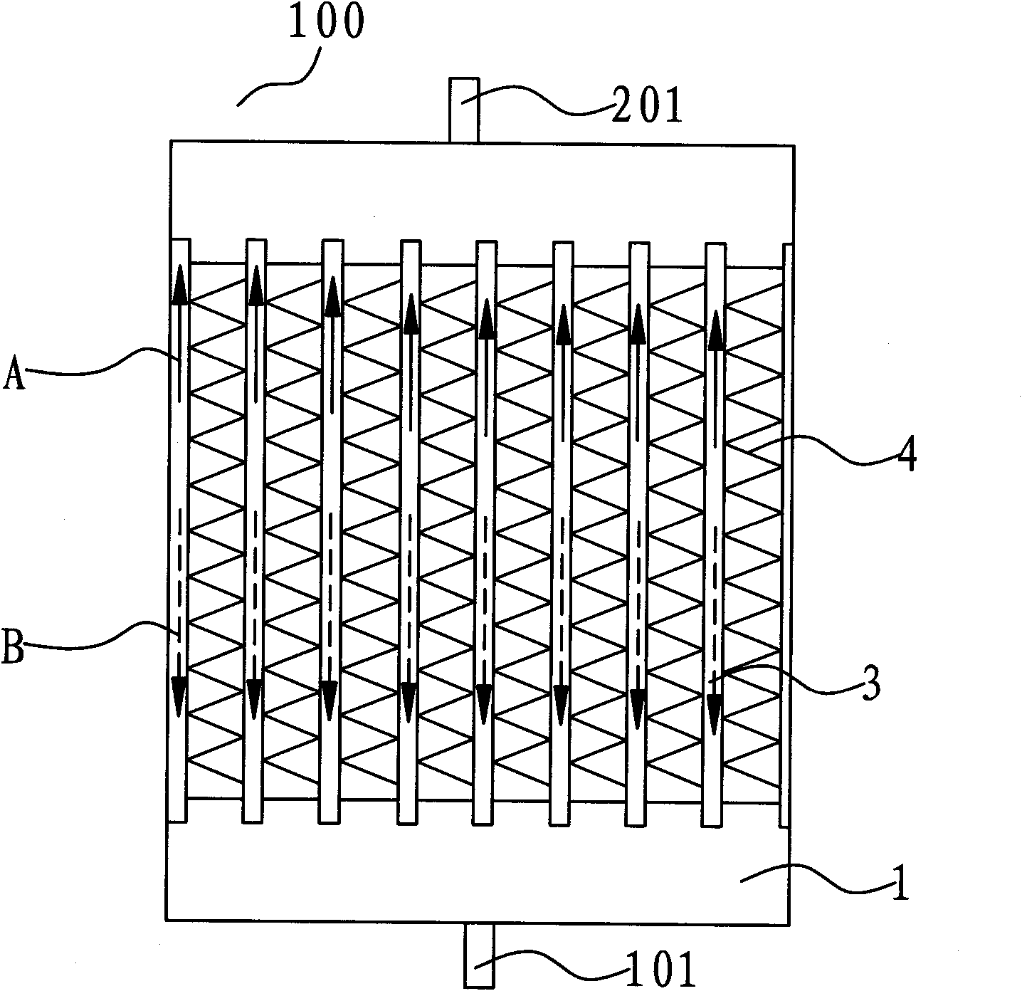

Image

  • Heat exchanging device and refrigerating system
  • Heat exchanging device and refrigerating system
  • Heat exchanging device and refrigerating system

Examples


Embodiment Construction

[0030] Embodiments of the present invention are described in detail below, examples of which are shown in the drawings, wherein the same or similar reference numerals designate the same or similar elements or elements having the same or similar functions throughout. The embodiments described below by referring to the figures are exemplary only for explaining the present invention and should not be construed as limiting the present invention.

[0031] In the description of the present invention, the orientations or positional relationships indicated by the terms "upper", "lower" and the like are based on the orientations or positional relationships shown in the drawings, which are only for the convenience of describing the present invention and do not require that the present invention must be based on a specific Azimuth configuration and operation, therefore, should not be construed as limiting the invention.

[0032] A heat exchange device according to an embodiment of the pr...


PUM


Abstract

The invention provides a heat exchanging device comprising a heat exchanger and a refrigerant flow direction changing unit, wherein the heat exchanger is provided with a first opening and a second opening; and the refrigerant flow direction changing unit is connected with the heat exchanger for changing the flow direction of a refrigerant in the heat exchanger. According to the heat exchanging device of the embodiment of the invention, for example, when used as an evaporator in a refrigerating system, the heat exchanging device can defrost through changing the flow direction of the refrigerant, reduce the reverse circulation defrosting time of the refrigerating system and even keep the temperature of cooled environment stable without using reverse circulation defrosting, and therefore, the refrigerating system can work more stably, and the efficiency of the refrigerating system is improved. The invention also provides a refrigerating system with the heat exchanging device.

Description

technical field [0001] The invention relates to a heat exchange device and a refrigeration system with the heat exchange device. Background technique [0002] The heat exchanger is an essential device in the heat pump system, and can be used as an outdoor unit and an indoor unit in the heat pump system. In the outdoor unit in winter, the heat exchanger is an evaporator. When the evaporation temperature is lower than zero, the moisture in the air around the surface of the evaporator will gradually frost. When the frost layer on the surface of the evaporator reaches a certain thickness, it will affect the cooling effect. Therefore, it is necessary to defrost the evaporator in time. In refrigeration or freezing applications, such as in cold storage, the indoor heat exchanger is used as an evaporator, operating in an extremely low ambient temperature, and a large amount of frost will accumulate on the surface of the evaporator, which will affect the heat transfer efficiency of ...

Claims


Application Information

Patent Timeline
Patent Type & Authority Applications(China)
IPC IPC(8): F25B47/00F25B41/04F25B49/02
CPCF25B47/025
Inventor 高强李艳星黄宁杰
Owner SANHUA HANGZHOU MICRO CHANNEL HEAT EXCHANGER
Learn More