Light guide board and its manufacturing method

A manufacturing method and technology of light guide plates, applied in optics, nonlinear optics, instruments, etc., can solve problems such as cumbersome manufacturing process, and achieve the effect of simple manufacturing process and uniform brightness of light output

Inactive Publication Date: 2005-07-20
HONG FU JIN PRECISION IND (SHENZHEN) CO LTD +1
View PDF1 Cites 2 Cited by
  • Summary
  • Abstract
  • Description
  • Claims
  • Application Information

AI Technical Summary

Problems solved by technology

[0005] In order to overcome the shortcomings of the complicated manufacturing process of the existing diffractive light guide plate, the present invention provides a light guide plate with simple manufacturing process and uniform light output brightness.

Method used


Image

  • Light guide board and its manufacturing method
  • Light guide board and its manufacturing method
  • Light guide board and its manufacturing method

Examples


Embodiment Construction

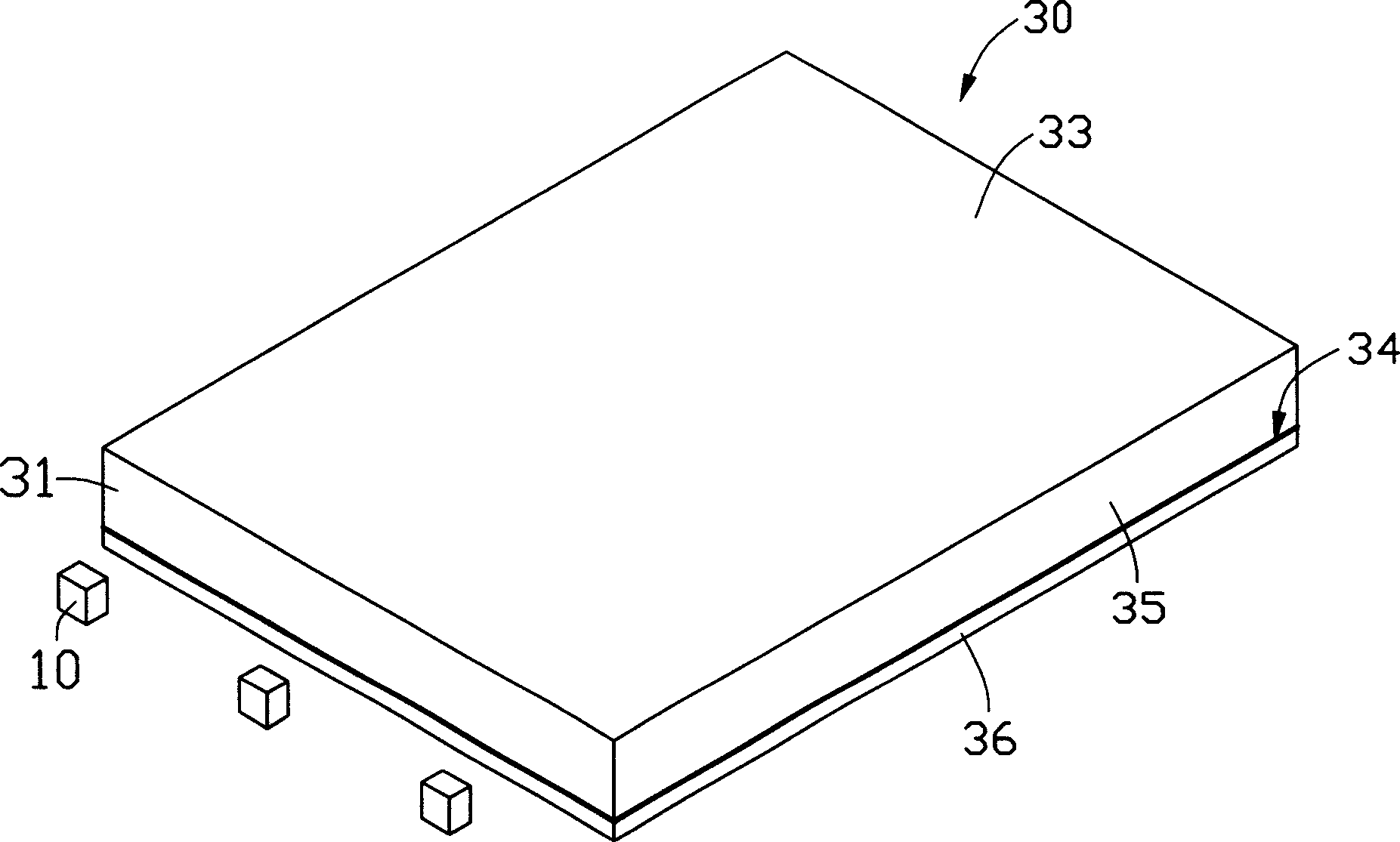
[0017] see figure 2 The light guide plate 30 of the present invention includes a light incident surface 31, a light exit surface 33 intersecting the light incident surface 31, a bottom surface 34 opposite to the light exit surface 33, and a plurality of side surfaces 35, and a reflective aluminum foil hologram 36 passes through the light guide plate 30 A transparent material (not shown) with matching refractive index is attached on the bottom surface 34 of the light guide plate 30 . The light emitted from the light source 10 enters the light guide plate 30 from the light incident surface 31 , passes through the transparent material through the bottom surface 34 of the light guide plate 30 , is diffracted by the reflective aluminum foil hologram 36 , and then uniformly exits from the light exit surface 33 . There should be no air gap between the light guide plate 30 and the reflective aluminum foil hologram 36, so that the light in the light guide plate 30 is directly emitted ...


PUM

PropertyMeasurementUnit
areaaaaaaaaaaa
depthaaaaaaaaaa
areaaaaaaaaaaa

Abstract

This invention provides a kind of light-transmitting board with well-proportioned light-out intensity and simple producing process. The light-transmitting board includes a light-in plane, a light-out plane crossed with the light-out one, a underside corresponding to the light-out plane and several side planes. The underside clings to a reflecting style of aluminum foil holographic slice designed on the basis of the digital computer holograph and on which equipped several reflecting pels organs with several first rasters. Besides this invention also provides the producing method of the light-transmitting board.

Description

【Technical field】 [0001] The invention relates to a light guide plate and a manufacturing method thereof. 【Background technique】 [0002] Liquid crystal displays have the advantages of lightness, thinness, and low power consumption, and are widely used in modern information equipment such as notebook computers, mobile phones, and personal digital assistants. Because the liquid crystal in the liquid crystal display itself does not have light-emitting properties, it needs to be provided with a surface light source to realize the display function. The surface light source and its light guide plate need to have higher brightness and uniformity of light output, so as to improve the color contrast of the liquid crystal display, the brightness effect of the full screen area, and the viewing angle. [0003] A prior art light guide plate such as figure 1 Shown is a diffractive light guide plate disclosed in European Patent No. 1,016,817 published on May 7, 2000. The upper surface ...

Claims


Application Information

Patent Timeline
Patent Type & Authority Applications(China)
IPC IPC(8): G02F1/1335
Inventor 张仁淙
Owner HONG FU JIN PRECISION IND (SHENZHEN) CO LTD
Why Eureka
Try Eureka