Pressure resisting type air pipe air leakage preventing structure of ventilation air conditioner system and air pipe joint machining method

An air-leakage-proof structure, air-conditioning system technology, applied in the direction of pipes/pipe joints/fittings, flange connections, passing components, etc., can solve unclear cognition, lack of thorough theoretical analysis of air leakage mechanism, unclear cognition of main areas, etc problem, to achieve the effect of simple processing, low input cost and reasonable design

Active Publication Date: 2016-07-20
SCEGC EQUIP INSTALLATION GRP COMPANY
View PDF6 Cites 8 Cited by
  • Summary
  • Abstract
  • Description
  • Claims
  • Application Information

AI Technical Summary

Problems solved by technology

[0005] Through the preliminary theoretical discussion and the quality tracking and scientific and technological novelty search of the whole process of metal air duct processing, assembly and installation, it is found that there are still some problems in the control of air leakage in the ventilation and air conditioning system, which are mainly manifested in the following five aspects: first, Existing research is unclear about the main areas of air leakage in the system; second, the impact of quality defects in each link of metal air duct production on air leakage

Method used


Image

  • Pressure resisting type air pipe air leakage preventing structure of ventilation air conditioner system and air pipe joint machining method
  • Pressure resisting type air pipe air leakage preventing structure of ventilation air conditioner system and air pipe joint machining method
  • Pressure resisting type air pipe air leakage preventing structure of ventilation air conditioner system and air pipe joint machining method

Examples


Embodiment 2

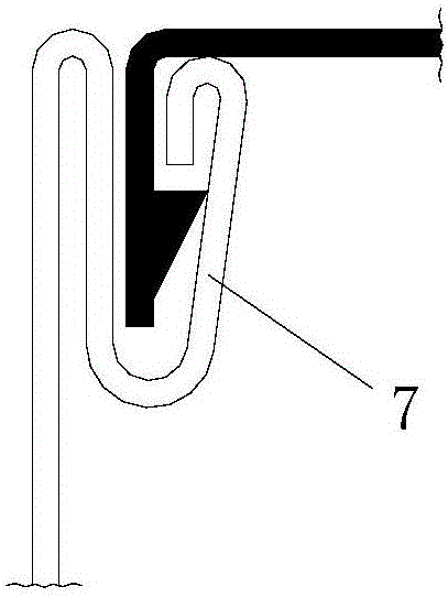
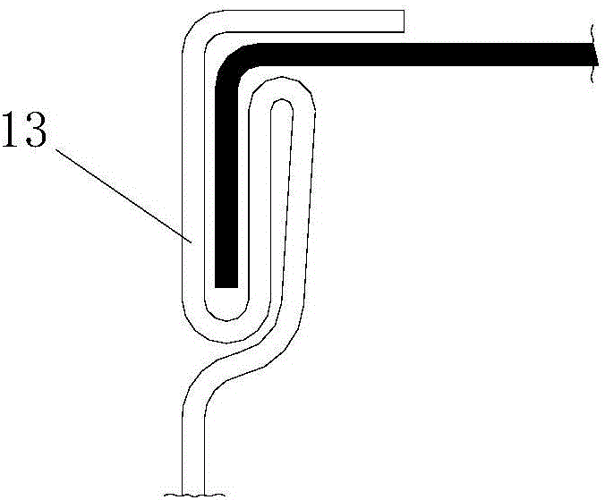
[0195] Such as Figure 5-2 with Figure 6-2 As shown, in this embodiment, the pressure-resistant metal air duct anti-leakage structure used for the ventilation and air-conditioning system is different from Embodiment 1. The two flange edges 2 of the angle steel flange are fixed on The air pipe section 1 or the right angle steel outside the connecting end of the connecting pipe fitting, and the connecting end of the air pipe pipe section 1 or the connecting pipe fitting is provided with a flange 4 fixed inside the right angle steel. The folding edge 4 is arranged parallel to the clamping strip 3-1 of the T-shaped sealing strip, and the clamping strip 3-1 is fastened and clamped between the folding edges 4 on the inner sides of the two flanges 2.

[0196] During actual installation, one right-angle side of the right-angle steel is fixed on the duct section 1 or the connecting pipe fitting, and the other right-angle side is arranged parallel to the clamping strip 3-1 of the T-shaped ...


PUM


Abstract

The invention discloses a pressure resisting type air pipe air leakage preventing structure of a ventilation air conditioner system. The pressure resisting type air pipe air leakage preventing structure comprises a pressure resisting type sealing structure and a clamping structure. The pressure resisting type sealing structure comprises a pressure resisting type sealing strip located between two flange edges of an air pipe flange. The clamping structure comprises a clamping piece clamped on the two flange edges. The pressure resisting type sealing strip is a T-shaped sealing strip. The T-shaped sealing strip comprises a clamping strip and a limiting strip located at the bottom of the clamping strip. The pressure resisting type air pipe air leakage preventing structure is simple, reasonable in design, convenient to install, good in using effect and capable of effectively reducing the air leakage amount of an air pipe of the ventilation air conditioner system. Meanwhile, the invention discloses an air pipe joint machining method. The method comprises the first step of metal panel cutting, the second step of seaming machining, the third step of flange machining edge machining, the fourth step of pipe joint body panel bending and the fifth step of seaming joint closing and compacting. The machining method is simple in step, manufacturing is easy and convenient, the using effect is good, and the air pipe joint machining process can be easily, conveniently and rapidly finished.

Description

Technical field [0001] The invention belongs to the technical field of construction of ventilation and air-conditioning systems, and in particular relates to a pressure-resistant air pipe anti-leakage structure of a ventilation and air-conditioning system and a method for processing air pipe sections. Background technique [0002] The ventilation and air-conditioning system is composed of a ventilation system and an air-conditioning system. The ventilation system is composed of blower, air duct, air duct components, muffler, etc.; while the air-conditioning system is composed of air conditioning cold and heat sources, air handlers, and air delivery pipes for transportation and distribution. And the air conditioner automatically controls and regulates indoor temperature, humidity, air velocity and cleanliness. Today, the energy consumption of ventilation and air conditioning systems due to air leakage is undoubtedly a major part of building energy consumption. In the ventilation ...

Claims


Application Information

Patent Timeline
IPC IPC(8): F16L23/16B23P15/00B21D39/02
CPCB21D39/02B23P15/00F16L23/162
Inventor 冯璐李兴武薛新铭胡春林秦文敏史均社房海峰
Owner SCEGC EQUIP INSTALLATION GRP COMPANY
Why Eureka
Try Eureka