Circuit device for poleless discharge lamp

A technology for circuit devices and discharge lamps, which is applied to the use of gas discharge lamps, lighting devices, electric light sources, etc., can solve the problems of difficult production or adjustment of circuit devices, easy damage of bidirectional trigger devices, and complex structures, and achieves simple structure, Effects of improving reliability and reducing size

Inactive Publication Date: 2005-07-20
任文华
View PDF1 Cites 1 Cited by
  • Summary
  • Abstract
  • Description
  • Claims
  • Application Information

AI Technical Summary

Problems solved by technology

This kind of circuit device is provided with a control circuit with complex structure, which makes the production or adjustment of the circuit device more difficult; in addition, this kind of circuit dev

Method used


Image

  • Circuit device for poleless discharge lamp
  • Circuit device for poleless discharge lamp
  • Circuit device for poleless discharge lamp

Examples


Example Embodiment

[0017] Described below in conjunction with embodiment and accompanying drawing:

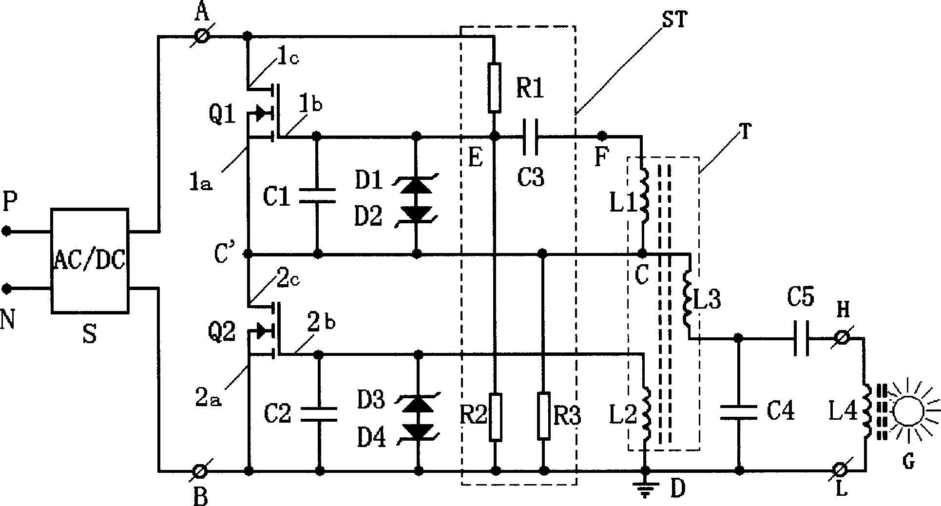
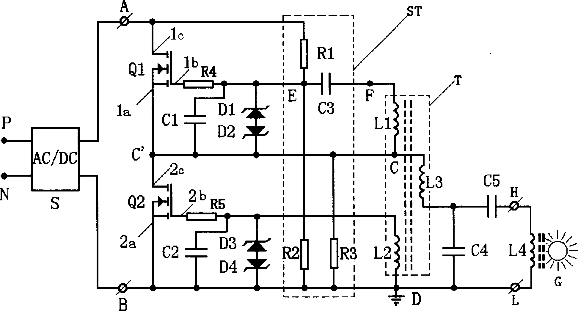
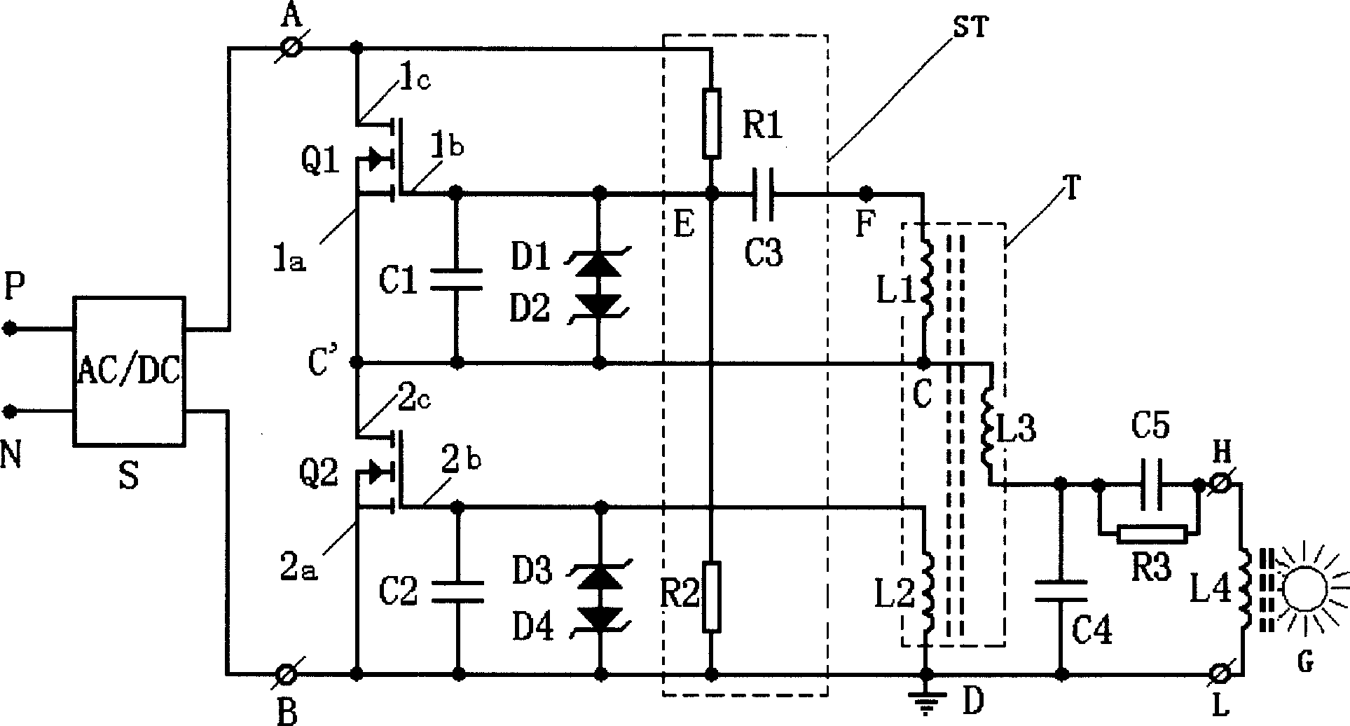
[0018] figure 1 A schematic structural diagram of the circuit arrangement of the present invention is shown. The DC voltage source S is an AC / DC converter, such as a DC voltage source obtained by bridge rectification of a 50Hz or 60Hz public AC power source, or a DC voltage source obtained by input filtering, bridge rectification and power factor conversion Voltage source, its input terminal is connected to the P and N poles of the common AC power supply, and its output has first and second output terminals A, B. A DC / AC converter circuit has a pair of power switches Q1, Q2 connected in series on the first and second output terminals A and B of the DC voltage source S. One main electrode 1c of the first power switch Q1 is connected to the first output terminal A, and the other main electrode 1a of the first power switch Q1 is connected to one main electrode 2c of the second power switch Q2. Th...


PUM


Abstract

The invention belongs to a discharge lamp control device, used in nonpolar discharge lamp and including circuit device of self-oscillating DC/AC converter, where the converter has resonant load loop, DC/AC converting circuit, drive control circuit and startup circuit. It uses the startup circuit without two-way trigger device and arranges a transformer with three windings and coking induction and driving induction, thus simplifying the structure of the circuit device, shortening the bulk and strengthening the operating reliability.

Description

technical field [0001] The invention relates to a control device for a discharge lamp. Background technique [0002] The electrodeless discharge lamp is a long-life high-efficiency light source, and there are many known circuit devices for controlling the operation of the electrodeless discharge lamp. The Chinese patent application No. 97123080.3 published on June 10, 1998 discloses a circuit device for an electrodeless discharge lamp. The circuit arrangement has a load circuit supplied with high-frequency power, a frequency generator for driving the load circuit and a control circuit for controlling the frequency generator. This kind of circuit device is provided with a control circuit with complex structure, which makes the production or adjustment of the circuit device more difficult; in addition, this kind of circuit device uses a conventional starting circuit with a bidirectional trigger device, and the bidirectional trigger device is easy...

Claims


Application Information

Patent Timeline
IPC IPC(8): H05B41/282
CPCY02B20/186Y02B20/185Y02B20/00
Inventor 任文华
Owner 任文华
Why Eureka
Try Eureka