Fluidized bed boiler furnace comprising two hearths separated by an inside leg area

A technology for fluidized bed boilers and partitions, which is applied in fluidized bed boilers, fluidized bed combustion equipment, steam boilers, etc., and can solve problems such as limiting panels

Inactive Publication Date: 2005-07-20
GENERAL ELECTRIC TECH GMBH
View PDF0 Cites 10 Cited by
  • Summary
  • Abstract
  • Description
  • Claims
  • Application Information

AI Technical Summary

Problems solved by technology

However, for boilers comprising two furnace chambers separated by a partition, this arrangement has the disadvantage that it limits the The number of panels on the side walls stated

Method used


Image

  • Fluidized bed boiler furnace comprising two hearths separated by an inside leg area
  • Fluidized bed boiler furnace comprising two hearths separated by an inside leg area
  • Fluidized bed boiler furnace comprising two hearths separated by an inside leg area

Examples


Embodiment Construction

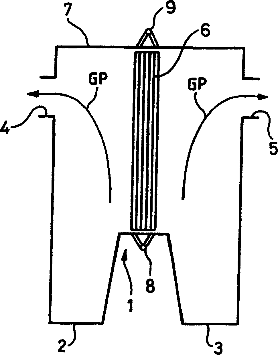
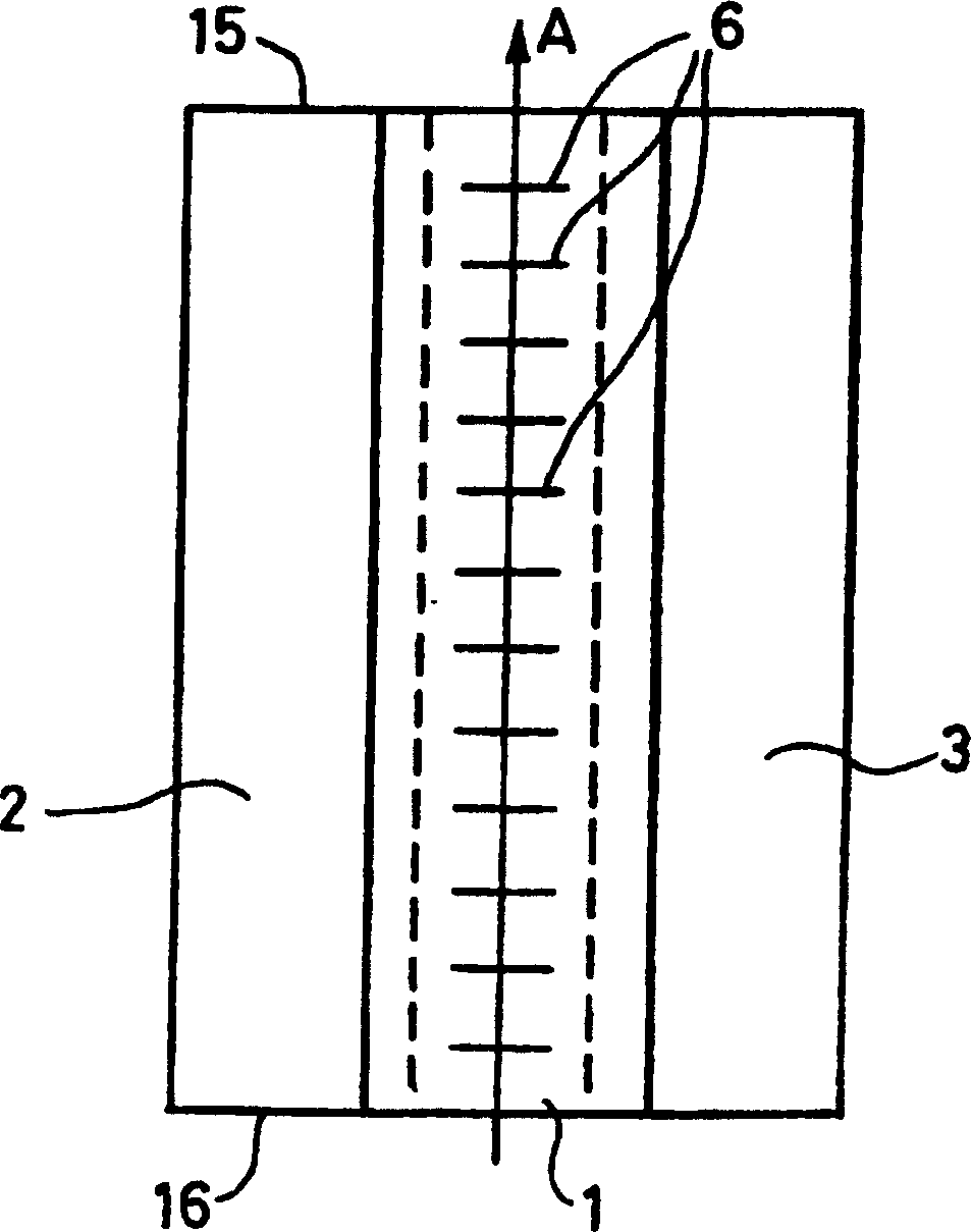
[0011] figure 1 The boiler shown in is a circulating fluidized bed (CFB) boiler in which the bottom forms a partition 1 separating the two furnace chambers 2 and 3 of the boiler. The outlets from the boiler to the cyclone are indicated by reference numerals 4 and 5 . The outlets to the cyclones are usually provided on the side walls of the boiler, and a boiler with a partition may include four or more outlets to the cyclones on either side of the partition.

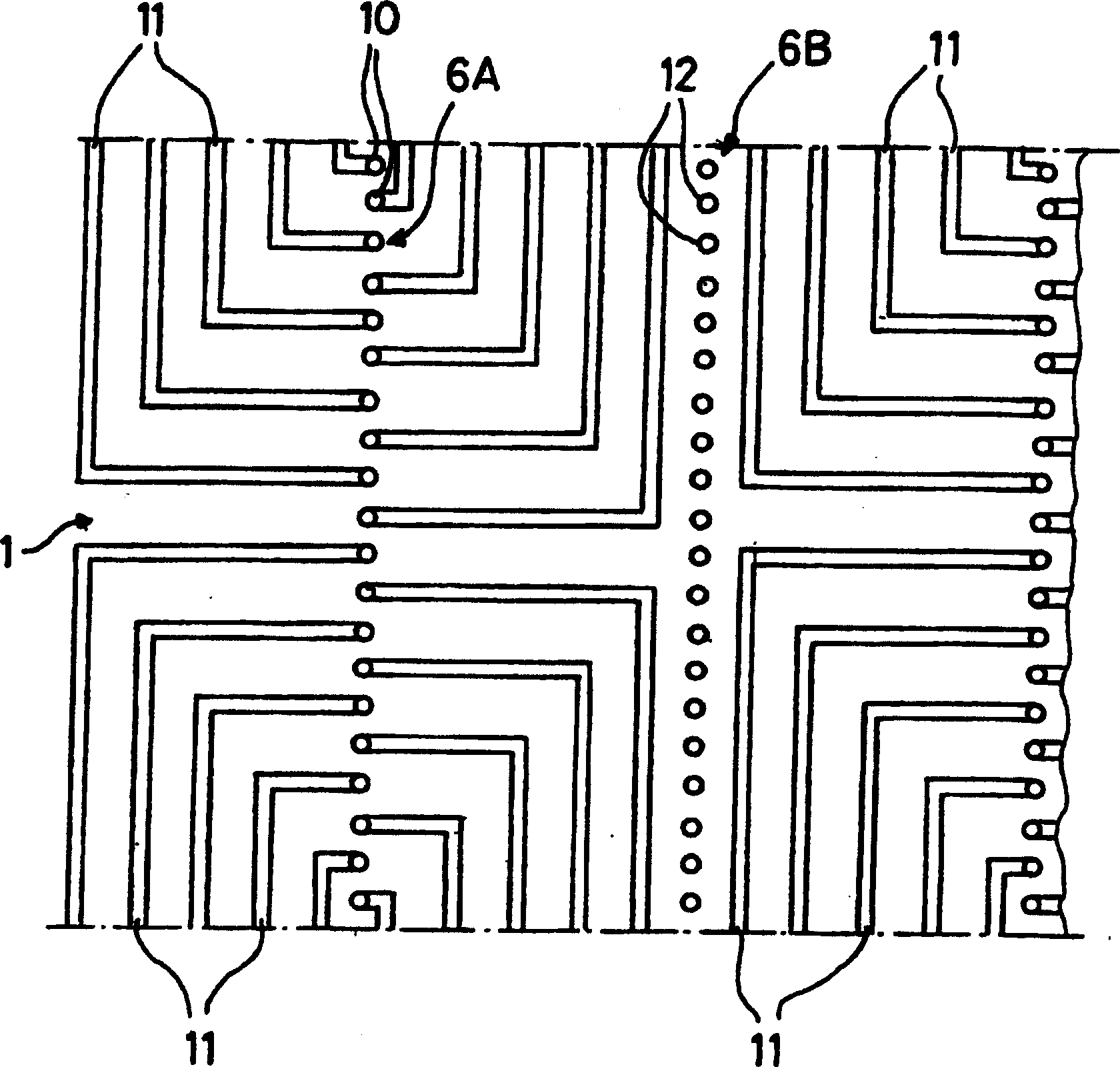
[0012] The boiler of the present invention is equipped with at least one heat exchange tube panel 6 arranged vertically on top of the partition 1 and perpendicular to the longitudinal direction A of the furnaces 2 and 3 so as not to hinder the circulation of gases and particles indicated by arrows GP , and thereby avoid pressure imbalances in the boiler. Each heat exchange tube panel 6 is fixed to the roof 7 of the boiler and is drawn between the roof and the partition to avoid unintentional vibration of the tubes in th...


PUM


Abstract

The fluidized bed boiler furnace provided with two hearths (2,3) separated by an inside leg area (1) in the lower part of the furnace comprises one or several panels (6) of heat exchange pipes each of which is disposed vertically above the inside leg area of the furnace and perpendicularly in relation to the longitudinal direction (A) of said hearths.

Description

technical field [0001] The invention relates to a fluidized bed boiler comprising two furnaces separated by a partition at the bottom of the boiler and at least one panel of heat exchange tubes. Background technique [0002] A circulating fluidized bed boiler of the aforementioned type is known, in particular from patent applications FR-91 / 03700 and FR-90 / 11859. It is known to install in a fluidized bed boiler one or more panels of heat exchange tubes filled with a heat transfer fluid such as water or an emulsion of water and steam. Each tube panel is generally positioned perpendicular to the boiler side wall and optionally secured thereto. However, for boilers comprising two furnace chambers separated by a partition, this arrangement has the disadvantage that it limits the The number of panels on the side walls described above. Contents of the invention [0003] The object of the present invention is to provide another arrangement of heat exchange tube panels utilizing...

Claims


Application Information

Patent Timeline
Patent Type & Authority Applications(China)
IPC IPC(8): F22B31/00F23C10/00
CPCF23C10/005F22B31/003
Inventor C·埃诺
Owner GENERAL ELECTRIC TECH GMBH
Why Eureka
Try Eureka