Pneumatic dust cleaning device of boiler

A soot cleaning device and boiler technology, which is applied in the field of boiler soot cleaning devices and pneumatic ash cleaning devices, can solve the problems of ineffective removal of soot deposits in refraction angles and horizontal flues, limited soot blowing energy of sonic waves, and soot blowing by steam. There are problems such as dead angles, so that the device is simple and effective, the device has high reliability, and the effect of ensuring safe operation

Active Publication Date: 2013-09-18
XIAN THERMAL POWER RES INST CO LTD
View PDF7 Cites 17 Cited by
  • Summary
  • Abstract
  • Description
  • Claims
  • Application Information

AI Technical Summary

Problems solved by technology

At present, the common soot removal devices on coal-fired power plant boilers include steam soot blowers, sonic soot blowers, and gas pulse soot blowers, etc., but they all have their own shortcomings, such as steam soo

Method used


Image

  • Pneumatic dust cleaning device of boiler
  • Pneumatic dust cleaning device of boiler
  • Pneumatic dust cleaning device of boiler

Examples


Embodiment Construction

[0021] The present invention will be described in further detail below in conjunction with the accompanying drawings.

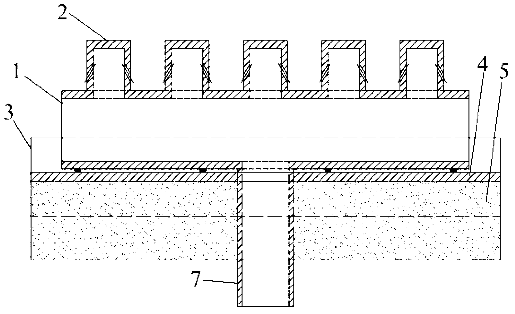
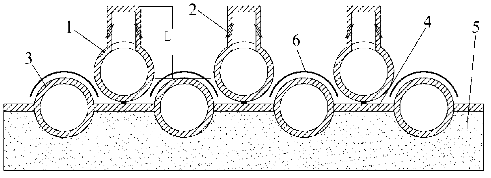
[0022] see figure 1 , 2, the present invention includes several groups of soot blowing tubes 1 installed on the diaphragm 4 between the boiler flame angle or the horizontal flue bottom wall tube 3, and several groups of soot blowing tubes 1 that are connected to each other and pass through the insulation insulation. The soot blowing medium conveying pipeline 7 of the hot layer 5, each group of soot blowing pipes 1 is arranged in sections along the flue gas flow direction, and is arranged in regions along the width direction of the flue. A soot blowing nozzle 2, in order to prevent the blowing damage of the lower wall pipe, the wear plate 6 made of heat-resistant and wear-resistant material is provided on the wall pipe.

[0023] In order to achieve independent and flexible control of soot blowing in different areas, the length of the soot blowing pipe along t...


PUM


Abstract

The invention relates to a pneumatic dust cleaning device for cleaning accumulated dust in a coal-fired boiler furnace arch and a horizontal flue. The accumulated dust piling friction is overcome and a dust accumulation layer is in the fluidization state by utilizing pneumatic (steam-driving), moving beds and fluidization theory, and ultimately the accumulated dust flows back to a hearth or is raised by the fume to be discharged through a cold dust funnel and a tail part flue, thereby achieving the dust cleaning effect. The dust cleaning device consists of components of dust blowing tubes, dust blowing nozzles (hoods), a wearing plate, dust blowing medium conveying pipelines, adjusting valves, a temperature measuring device, a control system and the like, wherein the dust blowing tubes are clung to a wall-surrounding tube film and arranged regionally, then flexible control in dust blowing in different areas is realized; and the distances and the relative angles of the dust blowing nozzles and wall-surrounding tubes can be selected according to demands. By utilizing the pneumatic dust cleaning device, the accumulated dust in the coal-fired boiler furnace arch and the horizontal flue can be effectively eliminated, a heated surface is kept clean, the efficiency of the boiler is improved, and the safety in operation of the boiler is ensured.

Description

technical field [0001] The invention belongs to the technical field of boilers, and relates to a boiler ash removal device, in particular to a pneumatic ash removal device for coal-fired boiler refraction corners and horizontal flue ash deposits. Background technique [0002] Boiler heating area ash is unmelted solid ash deposited on the heating surface, mainly occurs on the heating surface of the boiler panel superheater, reheater, economizer and air preheater. The ash in the heated area has become an important factor hindering the safe and economical operation of coal-fired generating units. The load requirement needs to increase the amount of fuel to increase the heat transfer, which will eventually lead to an increase in coal consumption of the unit; (2) Ash and slagging on the heating area will accelerate the corrosion of the heating surface pipes and shorten the service life of the heating surface; (3) Ash accumulation on the heating area Severe slag will lead to equi...

Claims


Application Information

Patent Timeline
IPC IPC(8): F23J1/06F23J3/02
Inventor 党黎军张宇博
Owner XIAN THERMAL POWER RES INST CO LTD
Why Eureka
Try Eureka