Multi-magnetic pole DC motor

A DC motor, multi-pole technology, applied in the direction of DC commutator, electrical components, electromechanical devices, etc., can solve the problems of current loss, large current, large energy consumption of DC motor, avoid mutual cancellation, increase density, The effect of improving work efficiency

Inactive Publication Date: 2005-08-10
陈维军
View PDF0 Cites 3 Cited by
  • Summary
  • Abstract
  • Description
  • Claims
  • Application Information

AI Technical Summary

Problems solved by technology

[0002] The current commonly used brushed DC motor requires a large amount of current, so it is not suitable for the production of high-power DC motors. The main reason for the high energy consumption of DC motors is that the use of the rotor coils is not perfect, because the current motor rotor coils are connected in series. , the magnetic fields generated by adjacent working coils cancel each other out partly, resulting in undue loss of current

Method used


Image

  • Multi-magnetic pole DC motor
  • Multi-magnetic pole DC motor

Examples


Embodiment Construction

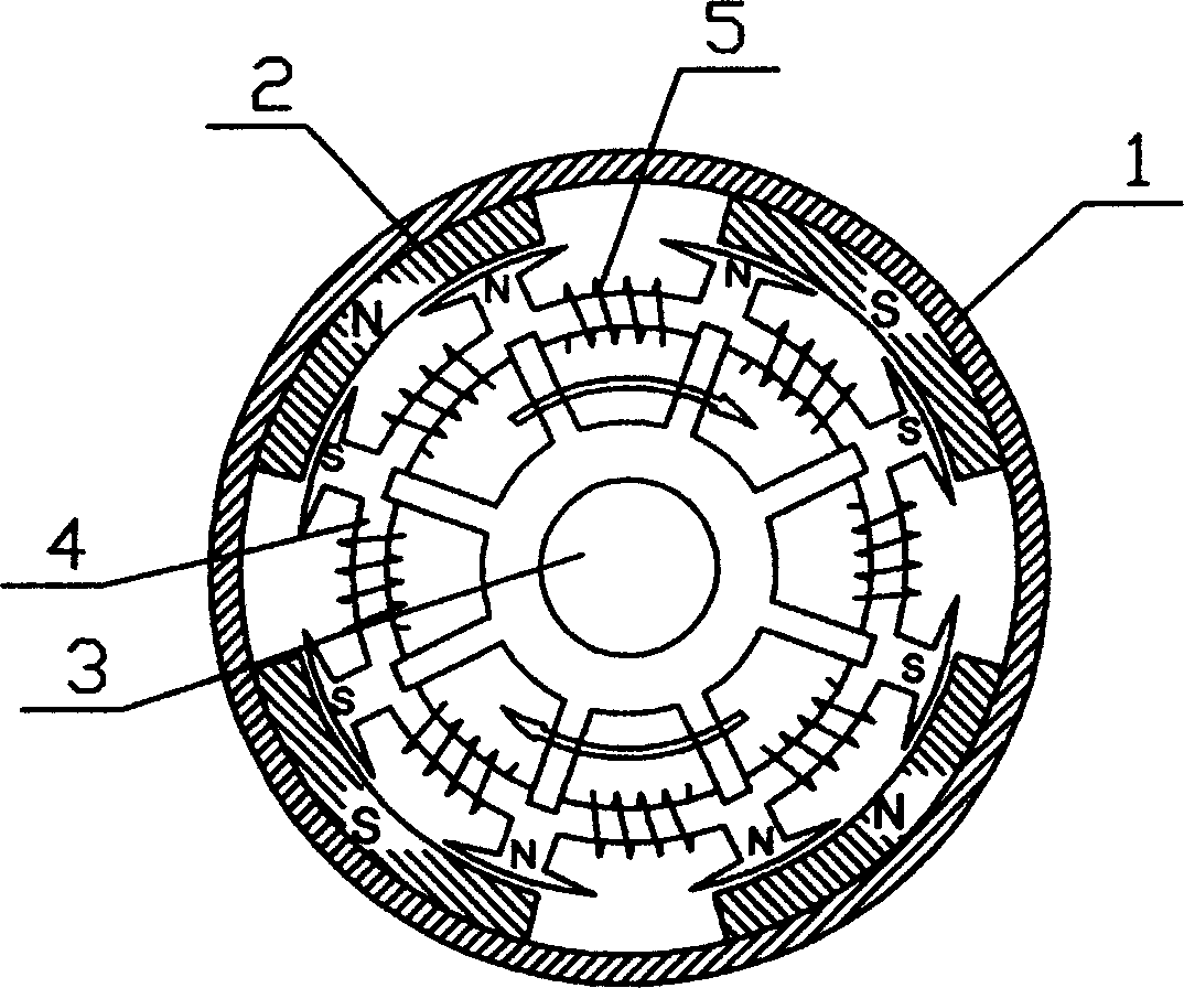
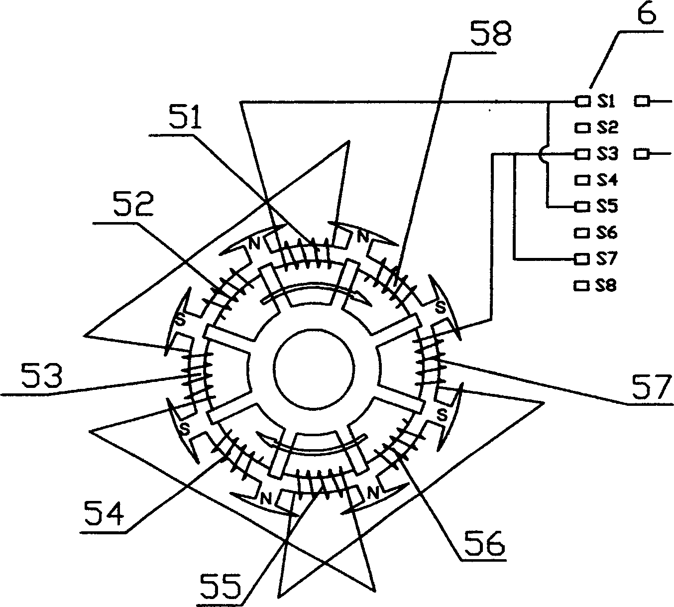
[0008] as attached figure 1 As shown, the multi-pole DC motor includes a casing 1, a stator 2 installed in the casing 1, a rotor core 4 installed on the rotating shaft 3, and an armature winding 5 wound on the rotor core 4 to generate magnetic flux , the converter 6 installed on the above-mentioned rotating shaft 3 and supplying power to the above-mentioned armature winding 5, the stator 2 is provided with two pairs of magnetic poles, and the number of coils of the armature winding 5 wound on the rotor core 4 There are 8 coils, and the intervals are divided into two working coil groups, the adjacent coils of each working coil group generate the same adjacent magnetic field poles, and the coils of each working coil group are connected in series with the The converter 6 is electrically connected.

[0009] The rotor of the present invention is different from the past. The number of slots of the rotor armature can be set according to the needs. The rotor has three major component...


PUM


Abstract

The disclosed DC motor includes following parts: chassis, stator installed inside chassis, rotor core setup at shaft, armature winding on core for generating magnetic beam, and converter installed on the shaft for supplying power to armature windings. There are at least more than two pairs of magnetic poles on the stator. Number of winding on armature is twice of number of stator pole. Multiple windings on armature are separated into two groups of winding. In each group, adjacent windings generate same magnetic pole so as to increase density of magnetic flux, or avoid cancel of magnetic flux. Thus, work efficiency of DC motor is increased. Cascaded windings in each group are connected to converter installed on shaft.

Description

technical field [0001] The invention relates to a direct current motor, in particular to a multi-magnetic pole direct current motor. Background technique [0002] The current commonly used brushed DC motor requires a large amount of current, so it is not suitable for the production of high-power DC motors. The main reason for the high energy consumption of DC motors is that the use of the rotor coils is not perfect, because the current motor rotor coils are connected in series. , the magnetic fields generated by adjacent working coils cancel each other out partly, resulting in undue loss of current. Contents of the invention [0003] The technical problem to be solved by the present invention is to provide a multi-magnetic pole DC motor which improves the utilization rate of current and reduces energy consumption. [0004] In order to achieve the above object, the technical solution of the present invention is: the multi-pole DC motor includes a casing, including a stator...

Claims


Application Information

Patent Timeline
Patent Type & Authority Applications(China)
IPC IPC(8): H02K16/00H02K23/26
Inventor 陈维军
Owner 陈维军
Why Eureka
Try Eureka