Eureka AIR delivers breakthrough ideas for toughest innovation challenges, trusted by R&D personnel around the world.

Base plate conveying device

A technology for conveying devices and substrates, which is applied in the direction of transportation and packaging, conveyor objects, program control manipulators, etc. It can solve the problem that the distance between a pair of arms 26 cannot be changed, and achieve the effect of simple structure and easy change of production arrangement

Inactive Publication Date: 2005-08-17
FUJI MASCH MFG CO LTD
View PDF1 Cites 4 Cited by
  • Summary
  • Abstract
  • Description
  • Claims
  • Application Information

AI Technical Summary

Problems solved by technology

[0004] In the transport device described in Patent Document 1, since the substrate S for LCD is placed on a pair of arms 26 for transport, the amount of deflection of the substrate S can be suppressed to be small, but since the center position cannot be changed, the The distance between the pair of arms 26, so when the distance between the arms 26 is adjusted according to the substrate S of different size, the center position between the pair of arms 26 will change, and the position of the transport device must be corrected due to the deviation of the center position.
[0005] In addition, since the pair of arms 26 is moved forward and backward between the holding position where the arm 26 protrudes toward the inspection device 10 and the retreat position where the arm 26 retreats from the inspection device 10 by moving the connecting member 39 in the Y direction, there is a device The problem of large-scale

Method used


Image

  • Base plate conveying device
  • Base plate conveying device
  • Base plate conveying device

Examples


Embodiment Construction

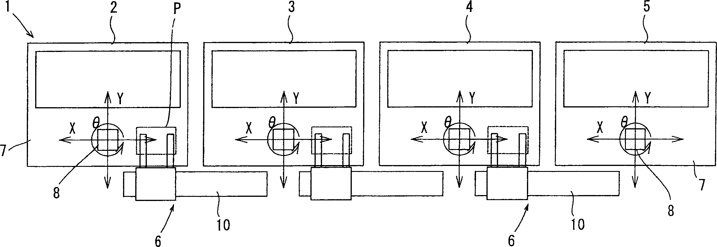
[0020] Next, the substrate transfer device of the present invention will be described with reference to the drawings. exist figure 1 Among them, 1 is a production line for mounting chips or thin films on a liquid crystal display panel (hereinafter referred to as a substrate) to produce a liquid crystal display device, which is composed of a cleaning device 2 for cleaning the terminals of the substrate P, pasting an anisotropic conductive film (ACF) The ACF attaching device 3 attached to the substrate P, the loading device 4 for mounting the printed chip or the film (FPC) of the circuit, and the crimping device 5 for pressing the loaded chip or FPC to be bonded to the substrate P are composed. The substrates are sequentially transported from the cleaning device 2 to the pressure-bonding device 5 , and the substrate transport device 6 is arranged across the adjacent devices. Each of the devices 2 to 5 is mounted with a stage 8 on the base 7, and each stage 8 moves linearly alo...


PUM


Abstract

The present invention provides a transport device with a simple structure and miniaturization, which can adjust the distance between a pair of holding arms holding a substrate without changing the central position, so that the pair of holding arms can rotate approximately Rotation is possible between 90 degree retracted positions. A pair of holding arms are respectively rotatably supported on a pair of arm supports movably mounted on the base in the transport direction, and each holding arm protrudes in a horizontal direction approximately at right angles to the transport direction to hold the substrate. It is rotated by a rotating device between the holding position of the holding position and the retracted position rotated approximately 90 degrees from the holding position. The arm supports are moved by an equal distance in conjunction with each other in directions opposite to each other in the conveying direction by the arm support body disconnecting device. The pair of arm supports holding the substrate are integrally moved in the transport direction by the transport moving device.

Description

technical field [0001] The present invention relates to a transport device for transporting substrates between devices. Background technique [0002] In Patent Document 1, there is disclosed a transport device 14 that holds a substrate S for LCD with a pair of load arms 26 (in the background art and problems of the invention, the reference numerals shown in Patent Document 1 are given). Below, the substrate S held on the arm 26 in a horizontal state is adsorbed to the hole 38 opened on the upper surface of the arm 26 and connected to the negative pressure device, and is transported into and out of the inspection device 10 . The conveying device 40 is equipped with an X stage 31 movably along the X direction on the base 32 , and a rotating body 30 is mounted on the rotating body 31 on the X stage 31 . A connecting member 39 to which a pair of arms 26 is fixed is supported on the mounted support plate 28 so as to be movable in the Y direction. The inspection device 10 can mo...

Claims


Application Information

Patent Timeline
Patent Type & Authority Applications(China)
IPC IPC(8): G02F1/13B25J9/02B25J15/06B65G49/05B65G49/06B65G49/07G02F1/1333H01L21/677H01L21/68
Inventor 矶贝武义龟谷泰范
Owner FUJI MASCH MFG CO LTD
Why Eureka
Eureka Blog
Learn More