Relative position information correction device, relative position information correction method, relative position information correction program, shape vector generation device, shape vector generat

A technology of relative position correction and shape vector, which is applied in the direction of measuring devices, image data processing, traffic control systems, etc., and can solve problems such as inability to display event occurrence points, position offsets, and display point offsets.

Inactive Publication Date: 2005-08-17
PANASONIC CORP
View PDF2 Cites 8 Cited by
  • Summary
  • Abstract
  • Description
  • Claims
  • Application Information

AI Technical Summary

Problems solved by technology

[0015] However, when the digital ground used by the encoder graph database with the digital ground used by the decoder graph database different, and when extending the shape vector, a problem arises: when the decoder displays the event occurrence point expressed as a position relative to the base node, a positional offset occurs
Also, not only the display point is offset, but additionally, the event occurrence point may not be displayed due to the difference in total length

Method used


Image

  • Relative position information correction device, relative position information correction method, relative position information correction program, shape vector generation device, shape vector generat
  • Relative position information correction device, relative position information correction method, relative position information correction program, shape vector generation device, shape vector generat
  • Relative position information correction device, relative position information correction method, relative position information correction program, shape vector generation device, shape vector generat

Examples


no. 1 example

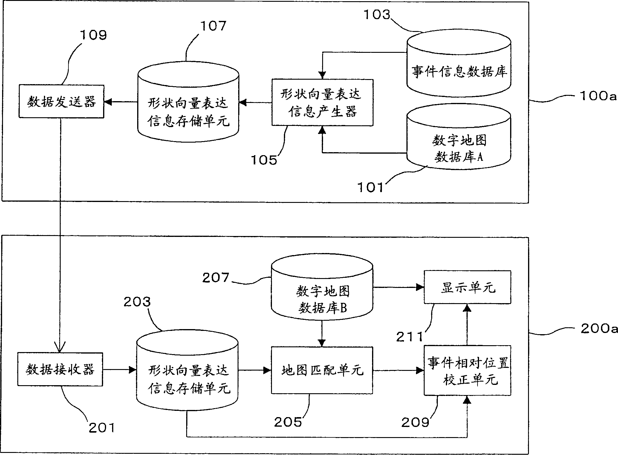
[0154] figure 1 It is a block diagram showing a car navigation system including a relative position information correction device according to the first embodiment of the present invention. Such as figure 1 As shown in, the relative position information correction device of this embodiment includes a sending device 100a and a receiving device 200a. The sending device 100a includes: a digital map database 101, which corresponds to the first place in claim 1 Graph database Event information database 103; shape vector expression information generator 105, which corresponds to the position expression conversion part and the first total length determination part; shape vector expression information storage unit 107; data transmitter 109. The receiving device 200a includes: a data receiver 201; a shape vector expression information storage unit 203; a map matching unit 205; a digital map database 207, which corresponds to the second place Graph database The event relative position c...

no. 2 example

[0183] Figure 5 It is a block diagram showing a car navigation system including a relative position information correction device according to the second embodiment of the present invention. in Figure 5 In, for and figure 1 Those overlapping parts in (First Embodiment) are provided with the same reference numerals, and no description is given for them. Such as Figure 5 As shown, the relative position information correction device used in the second embodiment includes a sending device 100b and a receiving device 200b.

[0184] In addition to the components of the transmitting device 100a in the first embodiment, the transmitting device 100b in this embodiment further includes: a shape vector compression / transformation processor 151, which corresponds to the shape vector compression / transformation in the claims Components; compressed shape vector expression information storage unit 153; compressed shape vector decoder 155, which corresponds to the first shape vector decoding c...

no. 3 example

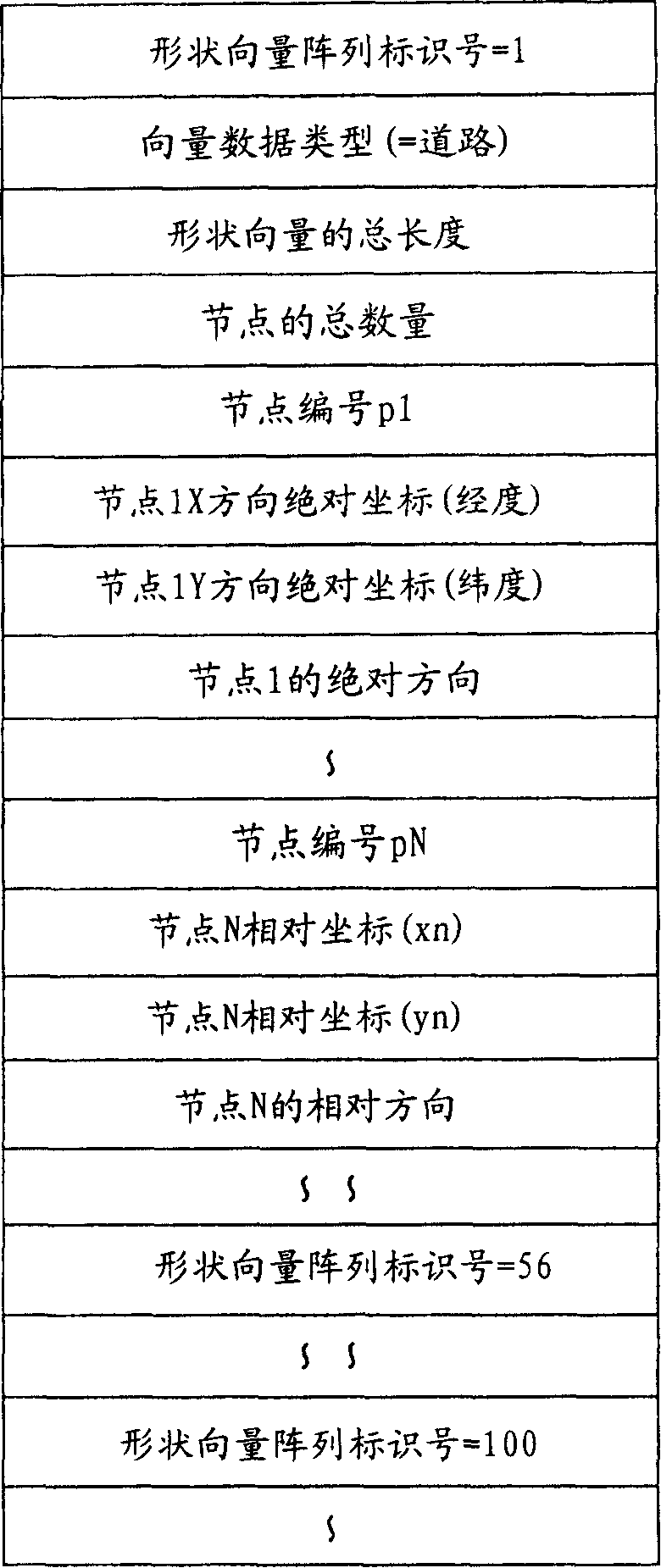
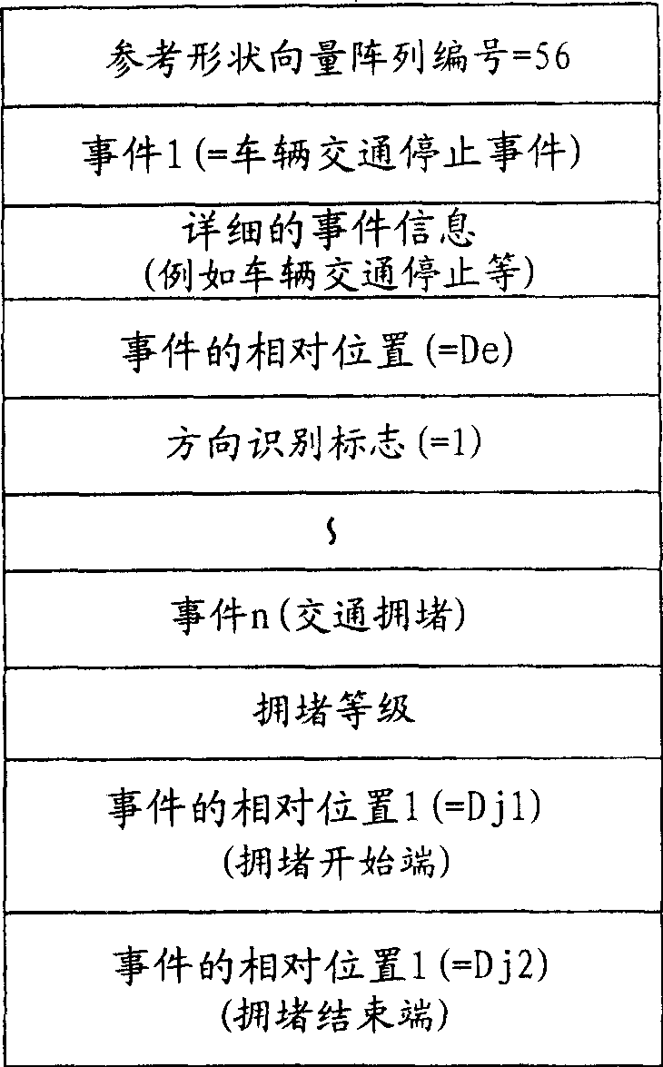
[0202]The configuration of the car navigation system including the relative position information correction device according to the third embodiment is the same as that of the second embodiment. However, in this embodiment, when the shape vector expression information generator 105 converts an event occurrence point into a relative position De in the shape vector, the event occurrence point is expressed as from a feature point (hereinafter referred to as The "feature node") expresses the relative position, such as the intersection point located at a certain large angle between the base point node at the start point and the opposite node at the end point. For example, the event occurrence point is represented as a point several hundred meters away from the characteristic node. In FIG. 8(b), an example data structure of the event information converted by the shape vector expression information generator 105 is shown. The example data structure of the shape vector data in FIG. 8(a) i...


PUM


Abstract

The objective of the present invention is to provide a relative location data correction apparatus, a relative location data correction method and a relative location data correction program that can cope with the shifting of a relative location between different digital map databases, and can accurately display a desired point.A relative position information correction device, a relative position information correction method, a relative position information correction program capable of absorbing a relative position shift between different digital map databases and correctly displaying a desired point. The relative position information correction device includes a transmission side device (100a) for transmitting to a reception side device (200a) event information such as an accident and traffic jam created according to the digital map database (101) and the reception side device (200a) for displaying an event occurrence point on the map indicated by the digital map database (207) according to the event information received from the transmission side device (100a) and performing position correction when displaying the event occurrence point. The transmission side device (100a) calculates the total length of the road section and transmits shape vector expression information including this total length to the reception side device (200a). The reception side device (200a) calculates the total length of the road section so as to correct the relative position of the event occurrence point by using the two total lengths.

Description

Technical field [0001] The present invention relates to a relative position information correction device, a relative position information correction method, and a relative position information correction program, which are used to absorb information in different digital places. Graph database The relative position offset between and is used to accurately display the desired point. The present invention also relates to a shape vector generation device, a shape vector generation method, and a shape vector generation program, which are used for digitally Graph database When a shape vector indicating a predetermined road section is generated from the map data stored in the map data, a feature node is set in the shape vector. Background technique [0002] Car navigation systems used in vehicles, for example, have the following functions: use digital ground Graph database And based on the location data obtained from the information received by the GPS receiver, to display a map of ...

Claims


Application Information

Patent Timeline
Patent Type & Authority Applications(China)
IPC IPC(8): G01C21/26G01C21/30G08G1/09G08G1/0967
CPCG01C21/30G08G1/092G08G1/096758G08G1/096716G01C21/26G08G1/096775G06T7/40G08G1/0969
Inventor 足立晋哉
Owner PANASONIC CORP
Why Eureka
Try Eureka