Particle source with selectable beam current and energy spread

A particle source and charged particle technology, applied in radiation/particle processing, circuits, discharge tubes, etc., can solve problems such as loose particle source structure

Active Publication Date: 2005-08-24
FEI CO
View PDF0 Cites 10 Cited by
  • Summary
  • Abstract
  • Description
  • Claims
  • Application Information

AI Technical Summary

Problems solved by technology

[0013] The existing particle source structure is relatively loose

Method used


Image

  • Particle source with selectable beam current and energy spread
  • Particle source with selectable beam current and energy spread
  • Particle source with selectable beam current and energy spread

Examples


Embodiment Construction

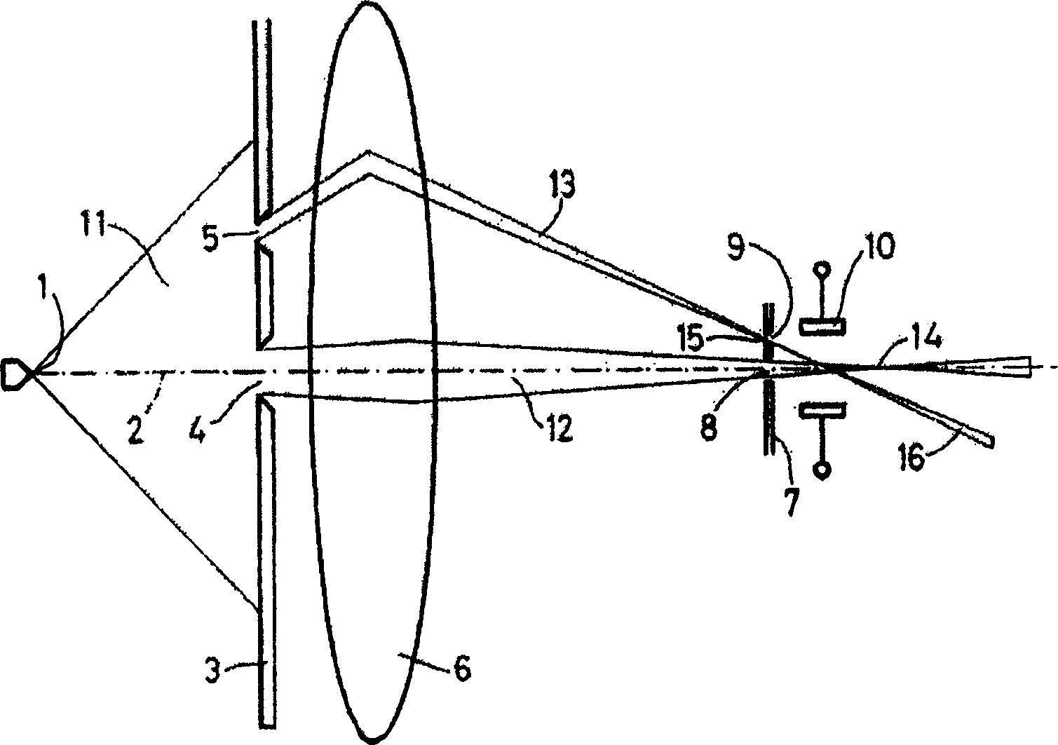
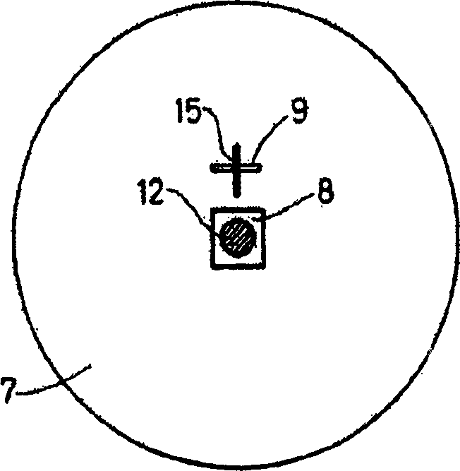
[0037] figure 1 The particle source of the present invention is schematically shown in section. A particle emission surface (for example an electron emission surface of an electron field emission source) 1 is located on an optical axis 2 . The electron beam 11 emitted from the electron emitting surface 1 is divided into a central particle beam 12 and an eccentric particle beam 13 by the diaphragm 3 having circular beam-limiting diaphragm openings 4 and 5 . Both particle beams 12 and 13 are focused by a lens 6 arranged on the optical axis 2 . The electron-emitting surface 1 is imaged by the lens 6 , the electron-emitting surface 1 forms an image 14 via the particle beam 12 and an image 15 via the particle beam 13 . The energy selection diaphragm opening 9 is located on the diaphragm 7, and a cutout 8 is also provided on the diaphragm 7 to allow the central particle beam 12 to pass through. In the vicinity of the position where the particle beam 13 passes the optical axis, a ...


PUM


Abstract

The invention describes a particle source in which energy selection occurs. The energy selection occurs by sending a beam of electrically charged particles 13 eccentrically through a lens 6. As a result of this, energy dispersion will occur in an image 15 formed by the lens 6. By projecting this image 15 onto a diaphragm 7, it is possible to only allow particles in a limited portion of the energy spectrum to pass. Consequently, the passed beam 16 will have a reduced energy spread. By adding a deflection unit 10, this particle beam 16 can be deflected toward the optical axis 2. One can also elect to deflect a beam 12 going through the middle of the lens 6 - and having, for example, greater current - toward the optical axis.

Description

technical field [0001] The invention relates to a particle-optical device provided with a particle source realized for generating at least one beam of charged particles, the particle source being provided with: [0002] a particle emitting surface for emitting charged particles; [0003] a lens to form an image of the surface from which the particles are emitted; [0004] a beam limiting diaphragm for confining the particle beam; and [0005] An energy selective diaphragm located at the image. Background technique [0006] S.Uhlemann and M.Haide published "For 200kv TEM" in the Proceedings of the "Fifteenth International Congress of Electron Microscopy" Conference 5 / S14 held in Durban, South Africa from September 1 to 6, 2002. "Experimental setup of an all-electrostatic monoenergizer" describes such a particle source for use in a particle-optical setup. [0007] The particle beam described in this document has the form of an electron source, which can be used in devices ...

Claims


Application Information

Patent Timeline
Patent Type & Authority Applications(China)
IPC IPC(8): G21K1/00G21K1/02H01J37/05H01J37/09H01J37/153H01J37/26
CPCH01J37/09H01J37/26H01J37/153H01J37/05
Inventor J·奇梅里克A·亨斯特拉
Owner FEI CO
Why Eureka
Try Eureka