Magnetic circuits of electrical machines

A technology of magnetic flux and stator, applied in the direction of magnetic circuit, synchronous generator, magnetic circuit static parts, etc., can solve the problems of increasing thermal characteristics, increasing power supply capacity, limiting time, etc.

Inactive Publication Date: 2005-08-24
SWITCHED RELUCTANCE DRIVES
View PDF0 Cites 2 Cited by
  • Summary
  • Abstract
  • Description
  • Claims
  • Application Information

AI Technical Summary

Problems solved by technology

The concomitant increase in current degrades the thermal characteristics, greatly limiting the time over which the motor can produce the required torque
Also, especially when the power source is a battery or other form of limited energy storage, a potential problem is that the need for extra current necessitates increasing the capacity of the power source

Method used


Image

  • Magnetic circuits of electrical machines
  • Magnetic circuits of electrical machines
  • Magnetic circuits of electrical machines

Examples


Embodiment Construction

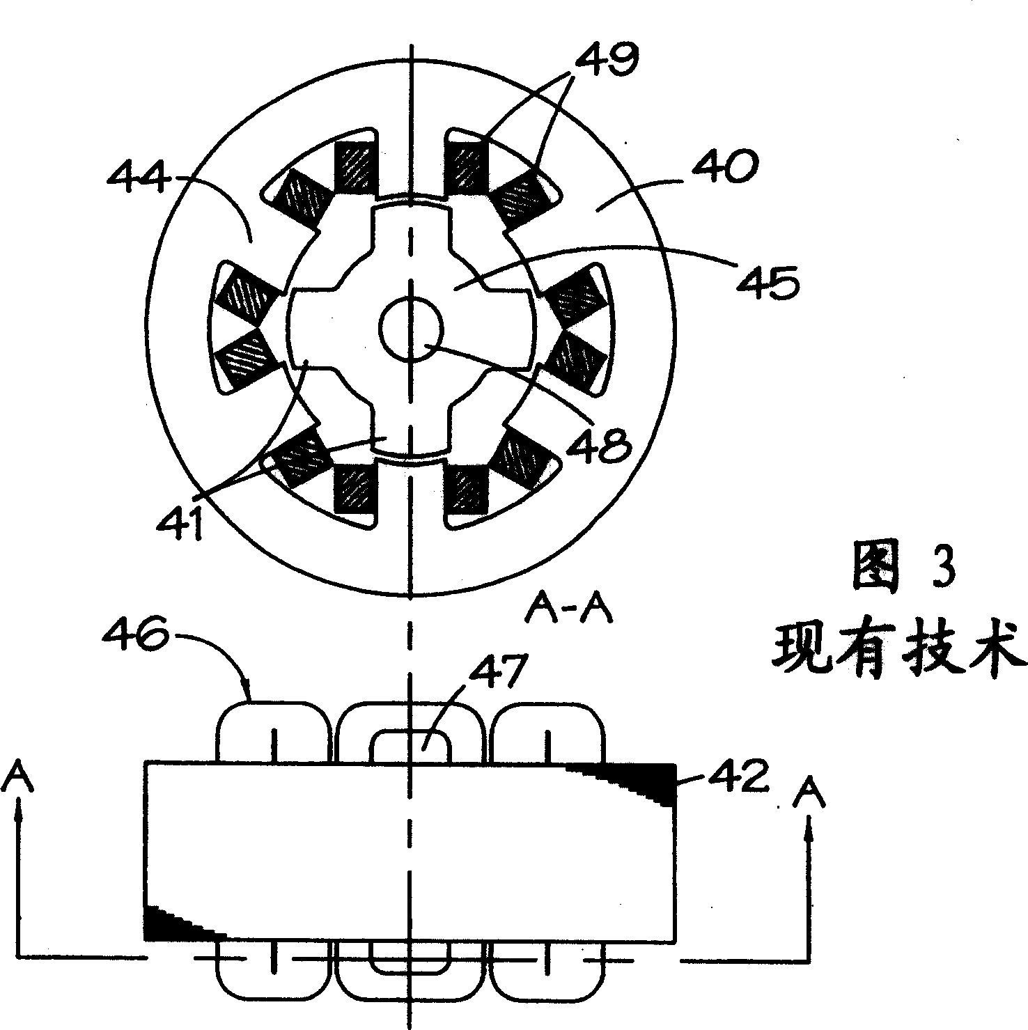
[0038] Figure 5 Stator flux plates are shown which are shaped to cooperate with the ends of stator core segments which, for example as shown in FIG. pole. The solid flux plate 50 has an annular portion 51 whose inner and outer diameters correspond to the back iron portion of the stator laminations. A plurality of teeth 52 project radially inwardly from the annular portion. Each tooth 52 is sized such that the tooth matches the shape of the stator pole 44, or the tooth is located slightly inward of the profile of the pole. The number of teeth on the flux plate is the same as the number of poles of the stator. The cross-sectional view of the flux plate shows that it has flat sides 53 adjacent to the end faces of the magnetizable lamination segments making up the stator core 42 . The teeth on the opposite side 54 of the flux plate are contoured to match the contour of the gap 47 (see FIG. 3 ) formed between the coil protrusion 46 and the extreme end. Figure 5 The illustrated...


PUM


Abstract

An electrical machine is provided with one or more flux plates at the end of the stator and rotor cores. On the stator side, the plate is profiled to substantially fill the void between the core and the winding. The plates are ferromagnetic and form part of the main magnetic circuit. They carry maximum flux at zero and low switching frequencies and substantially no flux at the highest operating speeds.

Description

technical field [0001] The present invention relates to improving the magnetic circuit of electric machines. The invention is particularly applicable to motors with raised plates, such as switched reluctance motors. Background technique [0002] The control and operation of switched reluctance motors is generally described in the paper "The Characteristics, Design and Applications of Switched Reluctance Motors and Drives", published in 1993 Presented by J.M. Stephenson and R.J. Blake at PCIM's 93 Conference and Exhibition, Nurnberg, Germany, 6.21-6.24, which is hereby incorporated by reference. In said paper, the "chopper" and "single-pulse" excitation modes of switched reluctance motors are described for low-speed and high-speed operation of the motor, respectively. [0003] Fig. 1 schematically shows a typical switched reluctance drive system in the prior art. It comprises a DC power source 11, either a battery or a rectified and filtered AC power source. The DC voltag...

Claims


Application Information

Patent Timeline
Patent Type & Authority Applications(China)
IPC IPC(8): H02K1/18H02K1/12H02K1/14H02K3/34H02K16/00H02K17/00H02K19/10H02K19/24H02K29/00
CPCH02K1/146H02K19/103H02K3/18
Inventor M·L·麦克莱兰
Owner SWITCHED RELUCTANCE DRIVES
Why Eureka
Try Eureka