Luminous device and illuminator

一种发光装置、照明装置的技术,应用在照明装置、照明装置的零部件、照明和加热设备等方向,能够解决发光装置发光强度以及亮度恶化、减少波长变换等问题

Inactive Publication Date: 2005-08-31
KYOCERA CORP
View PDF1 Cites 17 Cited by
  • Summary
  • Abstract
  • Description
  • Claims
  • Application Information

AI Technical Summary

Problems solved by technology

As a result, the effect of wavelength conversion by the phosphor is reduced, and there is a problem that the luminous intensity and brightness of the light-emitting device are significantly deteriorated.

Method used


Image

  • Luminous device and illuminator
  • Luminous device and illuminator
  • Luminous device and illuminator

Examples


Embodiment Construction

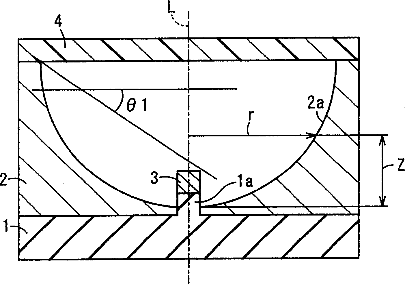
[0063] The specific implementation manners of the present invention will be described in detail below with reference to the accompanying drawings. figure 1 It is a cross-sectional view illustrating the light emitting device according to Embodiment 1 of the present invention. In the figure, the light emitting device includes a substrate 1 , a reflective component 2 , a light emitting device 3 and a phosphor layer 4 . A phosphor layer 4 for converting the wavelength of light emitted by the light emitting device 3 is provided on the upper part of the reflective member 2 .

[0064] The substrate 1 has a convex portion 1 a on its upper surface for mounting the light emitting device 3 . Also, wiring conductors (not shown) including lead terminals and metal-clad wiring for electrically connecting the inside and outside of the light-emitting device from the mounting portion 1b and its periphery are formed on the base body 1 . The reflective member 2 surrounds the convex portion 1a ...


PUM


Abstract

A light-emitting device has a light-emitting device (3), a base body (1) protruding section mounted the light-emitting device (3), a reflection member (2) and a fluorescent material layer (4) disposed with gap to the light-emitting device (3). A cross section of the inner circumferential surface (2a) of the reflection member (2) cut by a virtual plane including a virtual axis (L) penetrating a center of the inner surface and perpendicular to the upper principal surface of the base body (1) has a sectional profile defined by a curved line expressed by the following formula, and the inner surface of the reflection member is a curved surface obtained by rotating the curved line about the virtual axis: Z=(cr<2>) / [1+{1-(1+k)c<2>r<2>] ] <1 / 2>]} (wherein -1<=k<=-0.001, 0.001<=c<=10), r is the radius between the virtual axis and the surface of the inner circumferential surface, Z is the height from the lower end of the inner circumferential surface to the surface of the inner circumferential surface at the radius.

Description

technical field [0001] The invention relates to a light emitting device containing a light emitting device and a lighting device using the light emitting device. Background technique [0002] Figure 4 It is a sectional view for explaining a conventional light-emitting device. Figure 4 Among them, the light-emitting device is composed of a substrate 11 , a reflective member 12 , a light-emitting device 13 , and a phosphor layer 14 . The base body 11 is made of an insulator, and has a mounting portion 11a at the center of the upper surface for mounting the light emitting device 13 . In addition, the base body 11 is formed with wiring conductors (not shown) including lead terminals and metal-plated wirings that electrically connect the inside and outside of the light-emitting device from the mounting portion 11a and its surroundings. The reflection member 12 is formed in a frame shape. It is glued and fixed on the upper surface of the base body 11 . In addition, the inner ...

Claims


Application Information

Patent Timeline
Patent Type & Authority Applications(China)
IPC IPC(8): F21V7/06F21S4/00F21V7/22F21V9/08F21Y101/02H01L25/075H01L27/15H01L33/50H01L33/60
CPCH01L33/60H01L2924/0002H01L33/507H01L2924/00
Inventor 松浦真吾
Owner KYOCERA CORP
Why Eureka
Try Eureka