Magnetic condensing system for cryogenic engines

A low-temperature thermal and paramagnetic technology, applied in the direction of machines/engines, the magnetism of inorganic materials, and the operating mode of machines, can solve the problems of expensive superconducting electromagnetic coils and low power output

Inactive Publication Date: 2005-08-31
迈克尔・A・米诺维奇
View PDF1 Cites 5 Cited by
  • Summary
  • Abstract
  • Description
  • Claims
  • Application Information

AI Technical Summary

Problems solved by technology

While the engine works, converting natural thermal energy at room temperature into mechanical work, its power output is very small compared to its size and requires very expensive superconducting electromagnetic coils

Method used


Image

  • Magnetic condensing system for cryogenic engines
  • Magnetic condensing system for cryogenic engines
  • Magnetic condensing system for cryogenic engines

Examples


Embodiment Construction

[0021] Description of preferred embodiments

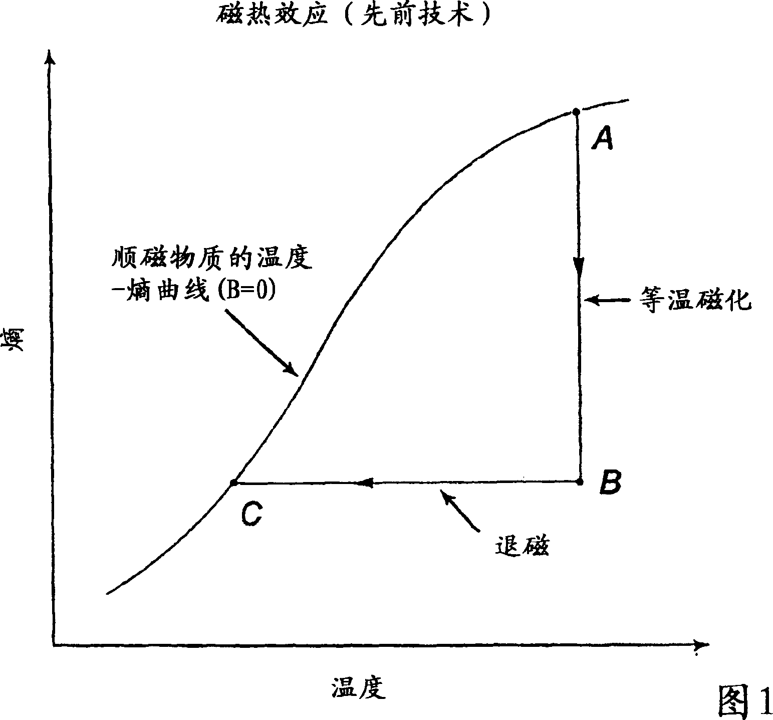
[0022] The basic physical principle utilized in the design of the magnetic condensation system described here is the principle of adiabatic demagnetization, also known as "magnetic cooling" or "magnetocaloric effect". Therefore, before describing the detailed design and operating characteristics of the magnetic condensation system, it is instructive to review the basic operating principles of adiabatic demagnetization and how these principles are applied to prior art magnetic refrigeration systems. This will provide a basic understanding of the unique working characteristics of the present invention, which can be easily distinguished from the prior art.

[0023] In making this comparison, it is important to point out and emphasize at the outset that all prior art "magnetic refrigeration systems" utilizing the magnetic cooling principle of adiabatic demagnetization employ paramagnetic substances in solid or powder form. In the pres...


PUM

PropertyMeasurementUnit
diameteraaaaaaaaaa
widthaaaaaaaaaa

Abstract

A method and apparatus is provided for generating an artificial heat sink below ambient temperature for a cryogenic condenser (32) by isothermally magnetizing a paramagnetic fluid and removing the magnetic field thereby creating a temperature drop in the fluid by the magentocaloric effect. The heat of magnetization is converted into mechanical work by initially placing the fluid inside a sealed chamber with a door (76) that opens to a conduit leading into the bore of a superconducting solenoid (72). When the solenoid (72) is energized with current, it creates a strong axial magnetic field that exerts magnetic attractive forces on the fluid inside the chamber. When the fluid is released by opening the door (76), it is accelerated through the conduit (70) toward the superconducting solenoid where it becomes magnetized by the increasing strength of the magnetic field. By mounting a non-magnetic turbine (120) inside the conduit between the solenoid and the chamber, the kinetic energy of the accelerating flow stream, which is equal to the heat of magnetization, is converted into mechanical work thereby achieving isothermal magnetization. By removing the magnetic field after the fluid enters the bore of the solenoid, a temperature reduction is achieved thereby enabling the fluid to absorb heat in a cryogenic condenser.

Description

Background of the invention [0001] It is well known to use a cryogenic engine to convert natural thermal energy in a room temperature environment into useful mechanical work. Basically, what the engine does is: compress a cryogenic working fluid such as liquid nitrogen at 77°K, pass it through a heat exchanger in thermal contact with the natural environment, thereby evaporating the cryogenic fluid into a compressed gas at room temperature, And the compressed gas is expanded by an expander, thereby converting a part of the absorbed natural heat energy into mechanical work. Unfortunately, since there is no natural heat sink at low temperatures, the expanded gas cannot recondense into a fluid at low temperatures, and recirculation through the engine produces more mechanical work in one cycle. Instead, the expanded gas has to be vented into the open atmosphere and cannot be recovered. Due to the high cost of liquefying cryogenic fluids, this technique of generating mechanical wo...

Claims


Application Information

Patent Timeline
Patent Type & Authority Applications(China)
IPC IPC(8): F01K25/10B64D27/02F25B1/00F25B21/00H01F1/00H01F1/01
CPCF25B2321/0021B64D27/02H01F1/012F25B21/00H01F1/0018Y02B30/66F01K27/005Y02B30/00F25B19/00
Inventor 迈克尔·A·米诺维奇
Owner 迈克尔・A・米诺维奇
Why Eureka
Try Eureka