Sputtering apparatus capable of changing distance between substrate and deposition preventing plate used for film formation
A kind of equipment and anti-plating technology, which is applied in the field of spray plating equipment for changing the distance between the substrate and the anti-plating sheet, and can solve problems such as not being improved.
- Summary
- Abstract
- Description
- Claims
- Application Information
AI Technical Summary
Problems solved by technology
Method used
Image

Examples
no. 1 example
[0026] Hereinafter, the first embodiment of the sputtering equipment of the present invention will be described with reference to the accompanying drawings.
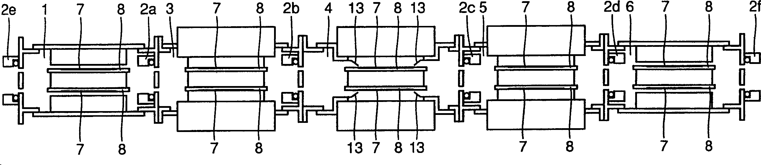
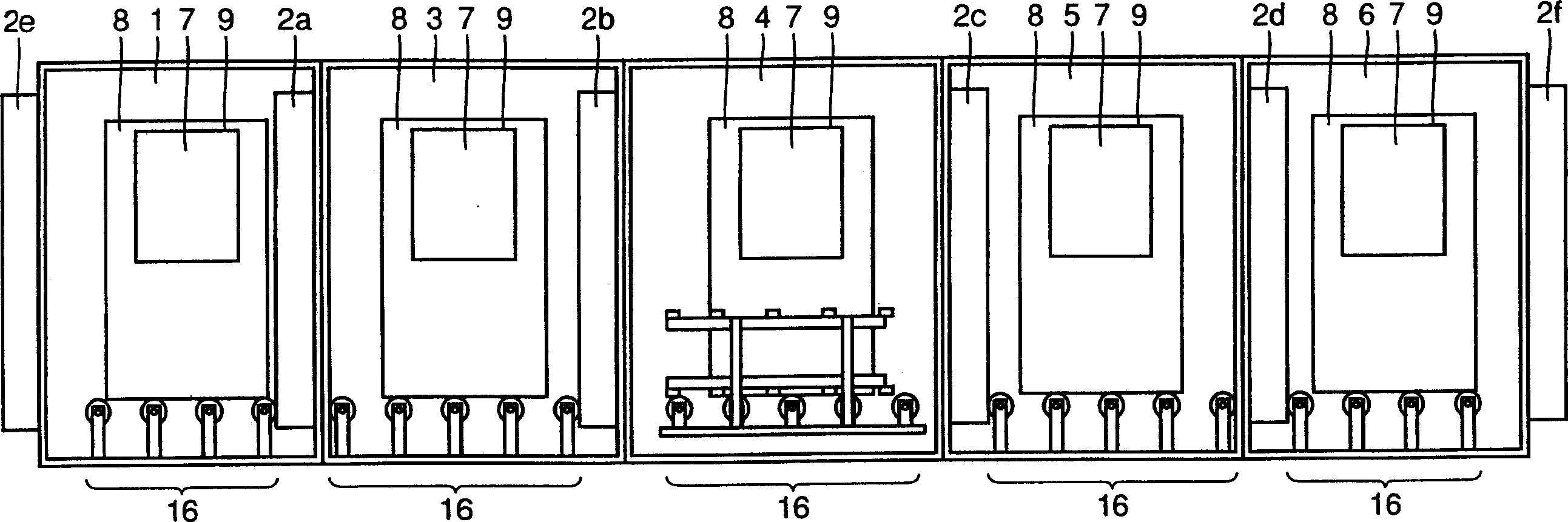
[0027] like figure 1 , 2 As shown, the spraying equipment includes a charging chamber 1, a heating chamber 3 connected to the charging chamber 1 through an openable and closable gate valve 2a, a film forming chamber 4 connected to the heating chamber 3 through an openable and closable gate valve 2b, and a film forming chamber 4 connected to the heating chamber 3 through an openable and closable gate valve 2b. The opening and closing gate valve 2c is connected to the cooling chamber 5 of the film forming chamber 4, and the unloading chamber 6 is connected to the cooling chamber 5 through the openable and closing gate valve 2d. Openable and closable gate valves 2e and 2f are provided at the inlet of the loading chamber 1 and the outlet of the unloading chamber 6, respectively.
[0028] like figure 1 , 2 As shown, the f...
no. 2 example
[0057] 5 and 6 are plan views of the main body, showing the internal structure of the film forming chamber 4 in the second embodiment of the sputtering device. Since the parts not shown in Figures 5 and 6 have the same figure 1 , 2 The structure shown in the first embodiment of the sputtering device is the same, so no specific repeated description will be given.
[0058] In the second embodiment, the film-forming chamber 4 of the sputtering equipment includes a plating protection sheet 23 with a plating protection sheet fixed part 23a and a plating protection sheet movable part 23b, a cooling water hole with positioning pins 11 and cooling water circulation The driving force transmission body 24 of 27, the mechanism 25 that introduces the driving force into the vacuum container, the driving force generating device 26 and the cooling water supply mechanism 28 that transmit the driving force to the film forming chamber (vacuum chamber) 4 through the mechanism 25.
[0059] The ...
no. 3 example
[0069] As a third embodiment, FIGS. 7 and 8 show an example of another structure of the anti-plating sheet 23 and its driving mechanism shown in FIGS. 5 and 6 . FIG. 7 shows the state of the film forming chamber 4 during film formation, and FIG. 8 is a plan view of the main body portion showing the inside of the film forming chamber 4 when the substrate is conveyed.
[0070] The plating resist 33 shown in FIGS. 7 and 8 has a positional relationship between the plating resist fixing portion 33a and the plating resist movable portion 33b opposite to that of the plating resist 23 shown in FIGS. 5 and 6 . Even with this structure, the sputtered film can be prevented from sticking to the portion of the substrate 7 where no film is to be formed and the substrate holder 8, and contact between the substrate 7 and the plating resist 33 can be prevented during conveyance.
PUM
 Abstract
Description
Claims
Application Information