Method and apparatus for transfer printing, and printed articles manufactured by same

Inactive Publication Date: 2011-07-14
SEO PAN SOO
View PDF12 Cites 0 Cited by
  • Summary
  • Abstract
  • Description
  • Claims
  • Application Information

AI Technical Summary

Benefits of technology

[0032]According to the present invention, there may be provided a printing or coating apparatus that achieves high-quality printing or coating of rough recycled paper or a packing box in a glazed sate.
[0033]That is, according to the present invention, as an image of a blanket is printed on a printing article by a transfer layer by forming an image layer on the blanket and forming the transfer layer on the blanket, highly glazed high-quality coating can be achieved on a printing article having a dark background or a rough surface.
[0034]In particular, as the blanket according to the present invention is made of one material selected from a plastic including oriented polypropylene (OPP) or PET (polyethylene terephthalate) having low surface energy, a synthetic resin, silicon, stainless steel, and aluminum, an image of the blanket can be easily transferred to the printing substrate. Further, as an

Problems solved by technology

Meanwhile, when a surface of a printing substrate is not smooth like in a packing box or recycled paper, printing quality deteriorates, failing to satisfy visual satisfaction.
However, in the conventional transfer printing method, as transfer paper is cut into a predetermined size to be used in a sheet form, there is a limit in reusing the transfer paper, which is non-economical and inefficient.
That is, a plastic film formed as a release layer or release paper is wasted and disposed after being used once or twice, consumption of resources is severe and the prices of printing articles increase.
Besides, as the method requires a number of manual works, it is impossible to repeat high speed transfers and products are not uniform, making the quality of the pri

Method used


Image

  • Method and apparatus for transfer printing, and printed articles manufactured by same
  • Method and apparatus for transfer printing, and printed articles manufactured by same
  • Method and apparatus for transfer printing, and printed articles manufactured by same

Examples


embodiment 1

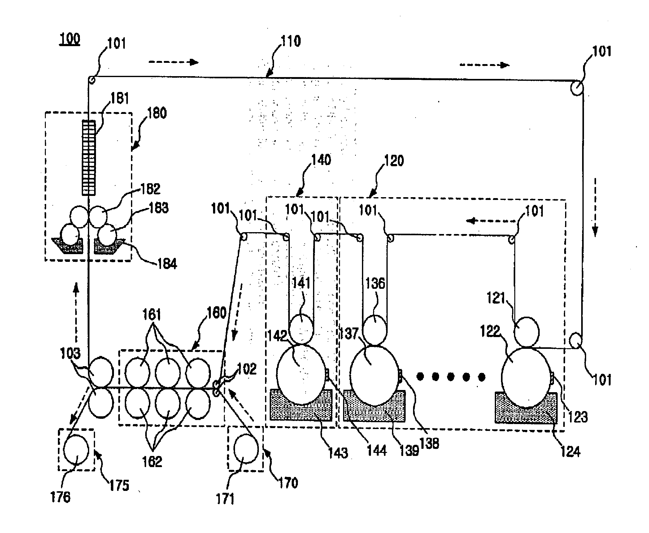
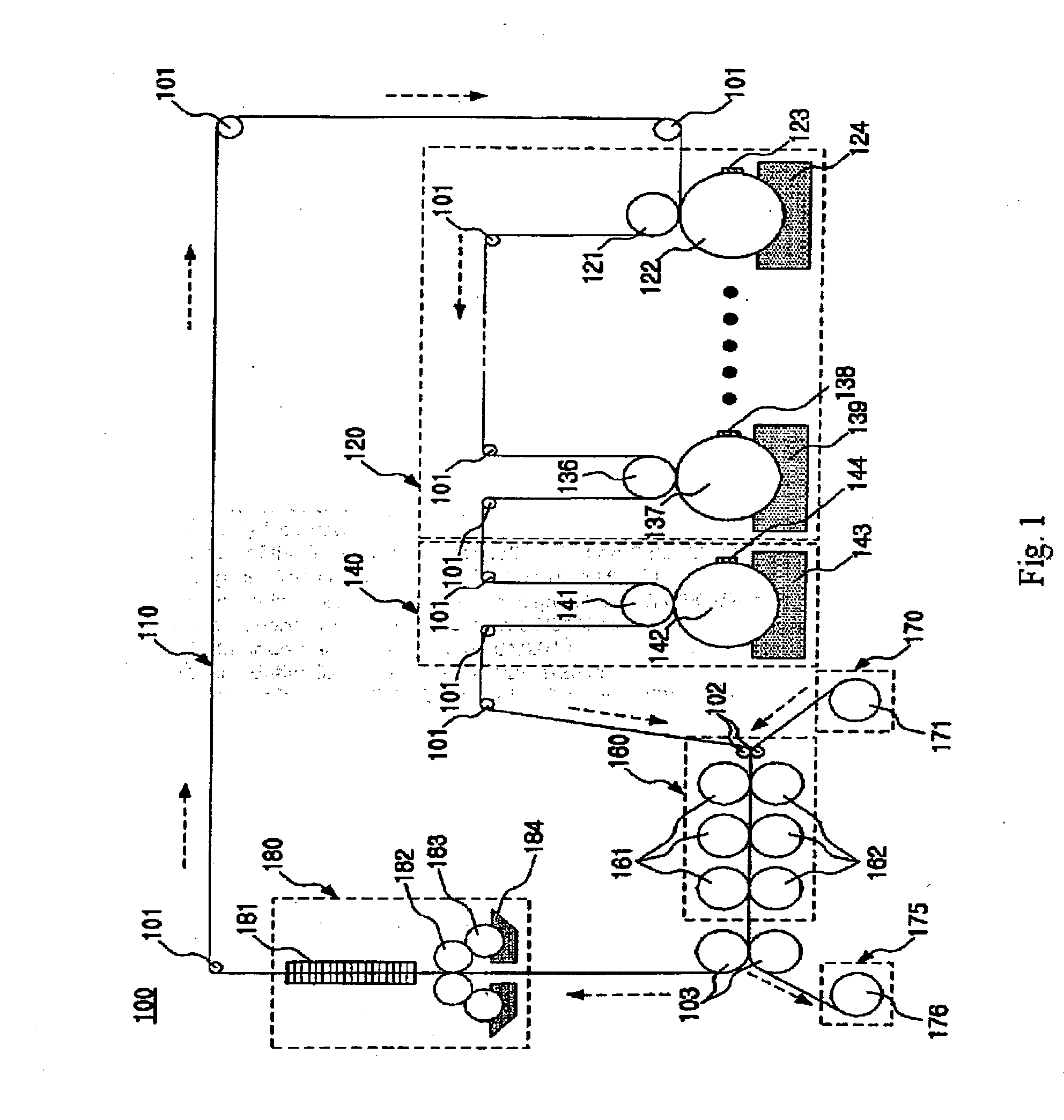
[0059]First, a transfer printing apparatus according to the first embodiment of the present invention will be described with reference to FIG. 1.

[0060]FIG. 1 is a systematic diagram of a printing apparatus according to the first embodiment of the present invention.

[0061]As illustrated in FIG. 1, a transfer printing apparatus (hereinafter, briefly referred as ‘a printing apparatus’ for convenience’ sake) 100 includes a blanket 100, a plurality of feed rollers 101, a blanket printing unit 120, a transfer layer forming (mixed solution applying) unit 140, a printing substrate printing unit 160, a printing substrate 170, a printing body 175, and a washing unit 180.

[0062]The blanket 110 receives printing ink from a cylinder and transfers it to the printing substrate 170 while making a printing pressure uniform, and functions to feed an ink layer of an image that will be printed on the printing body 170.

[0063]The blanket 110 is formed in an endless orbit and is made of one material selecte...

embodiment 2

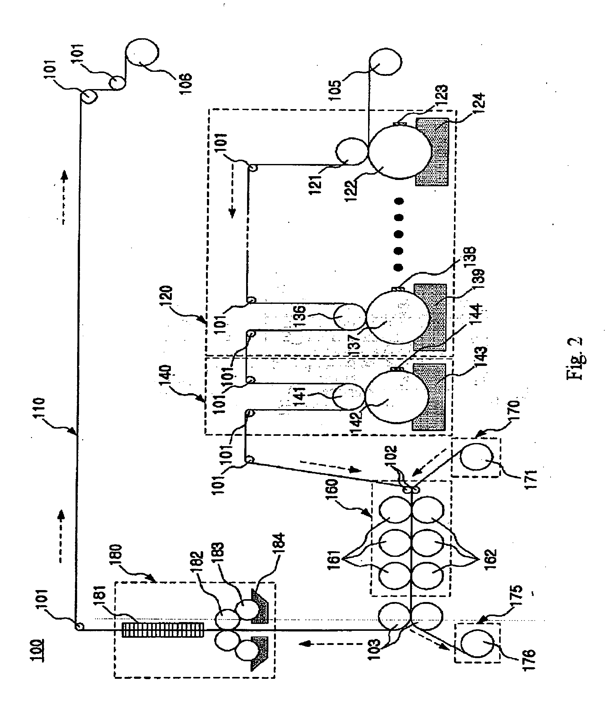
[0092]Hereinafter, a printing apparatus according to the second embodiment of the present invention will be described with reference to FIG. 3.

[0093]FIG. 3 is a systematic diagram of a printing apparatus according to the second embodiment of the present invention.

[0094]As illustrated in FIG. 3, the printing apparatus 200 according to the second embodiment of the present invention is substantially the same except that the transfer layer forming unit, i.e. the mixed solution applying unit 140 is replaced with an adhesive applying unit 240.

[0095]In the adhesive applying unit 240, a water-soluble dry adhesive is accommodated in the adhesive tank 243.

[0096]An adhesive roller 242 applies an adhesive on a surface of a blanket 210 by rotation thereof. The doctor blade 244 flattens a surface of the adhesive roller 242.

[0097]A press cylinder roller 241 is engaged with the adhesive roller 242 to be rotated. The adhesive of the adhesive roller 242 is applied on the surface of the blanket 210 wh...

embodiment 3

[0101]Hereinafter, a printing apparatus according to the third embodiment of the present invention will be described with reference to FIGS. 5 and 6.

[0102]FIG. 5 is a systematic diagram of a blanket printing apparatus. FIG. 6 is a systematic diagram of a printing apparatus according to the third embodiment of the present invention.

[0103]As illustrated in FIGS. 5 and 6, the printing apparatus 350 according to the third embodiment of the present invention is used in the case of not including an apparatus for printing a blanket 310.

[0104]The blanket 310 is prepared in a state in which an image is printed on a surface of the blanket 310 by the blanket printing apparatus 300 of FIG. 5.

[0105]Thereafter, the blanket 310 is installed at a releasing roller 306 and a winding roller 307 of the printing apparatus 350 to perform a transfer printing operation.


PUM

PropertyMeasurementUnit
Surface temperatureaaaaaaaaaa
Ratioaaaaaaaaaa
Transparencyaaaaaaaaaa

Abstract

The invention provides a transfer printing (coating) method, a transfer printing (coating) apparatus, and a printing article manufactured by the same. The transfer printing (coating) apparatus is adapted to achieve high quality printing and coating on a rough and unglazed surface, and includes: a blanket; a plurality of feed rollers installed along a feed direction of the blanket and configured to aid feeding of the blanket; a blanket printing unit configured to print an image on one surface of the blanket; a mixed solution applying unit configured to apply a mixed solution containing ink and nylon powder on. an image ink layer of the blanket; a printing substrate; a printing substrate printing unit configured to attach the ink and the nylon powder applied on the blanket to the printing substrate by thermally pressing the blanket to one surface of the printing substrate; and a printing body configured to accommodate the printing substrate printed by the printing substrate printing unit.

Description

TECHNICAL FIELD[0001]The present invention relates to a transfer printing (coating) method, a transfer printing (coating) apparatus, and a printing article (coating article) manufactured by the same, and more particularly to a technology of achieving high quality printing and coating on a rough and unglazed surface at a high speed.BACKGROUND ART[0002]In general, images are printed on a surface of paper for public relations wordings or decorations of a manufacturer by using a printing apparatus.[0003]Such printings are achieved by a variety of methods according to materials or characteristics of printing substrates such as paper. Meanwhile, when a surface of a printing substrate is not smooth like in a packing box or recycled paper, printing quality deteriorates, failing to satisfy visual satisfaction.[0004]In particular, in a conventional transfer printing method, after an image area is formed by applying a release agent to a surface of a plastic film or paper through a gravure prin...

Claims


Application Information

Patent Timeline
IPC IPC(8): B41F7/02
CPCB41F17/007B41M5/0358B41M5/035B41M5/025B41J2/11B41M5/398B41M5/40
Inventor SEO, PAN SOO
Owner SEO PAN SOO
Why Eureka
Try Eureka