
Energy collection type wind energy power station by pipe conveying

An energy-collecting, power station technology, applied in the field of wind-collecting ultra-large-capacity wind power generation devices, can solve the problems of high maintenance costs, high equipment investment, high power costs, etc., to achieve less energy consumption, more power, and reduced wind energy loss Effect

Inactive Publication Date: 2005-09-07
徐江荧
View PDF0 Cites 2 Cited by
  • Summary
  • Abstract
  • Description
  • Claims
  • Application Information

AI Technical Summary

Problems solved by technology

Therefore, the equipment investment is high, and the maintenance cost is high, the reliability is low, and the power cost of production is high.

Method used


Image

  • Energy collection type wind energy power station by pipe conveying
  • Energy collection type wind energy power station by pipe conveying
  • Energy collection type wind energy power station by pipe conveying

Examples


Embodiment Construction

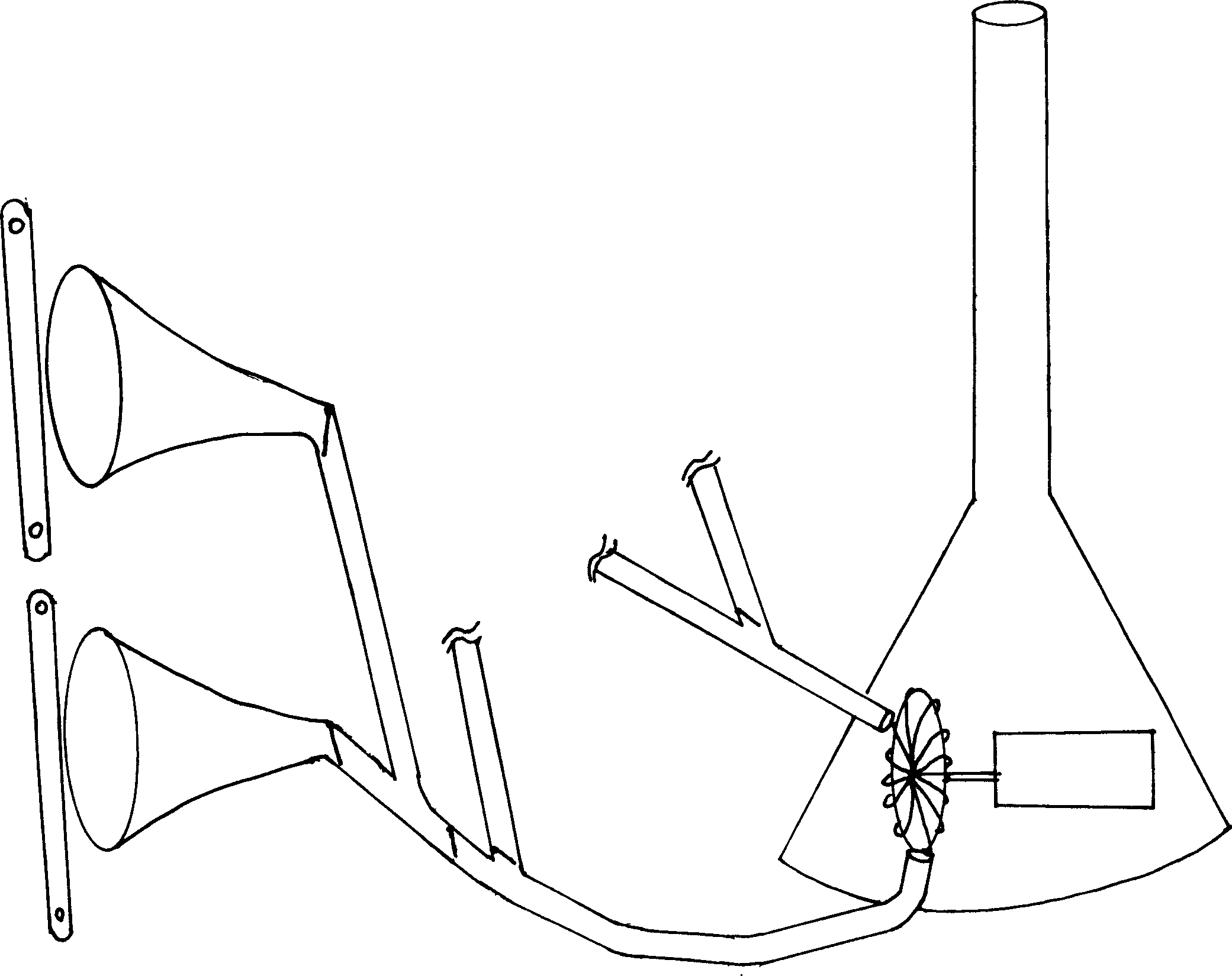
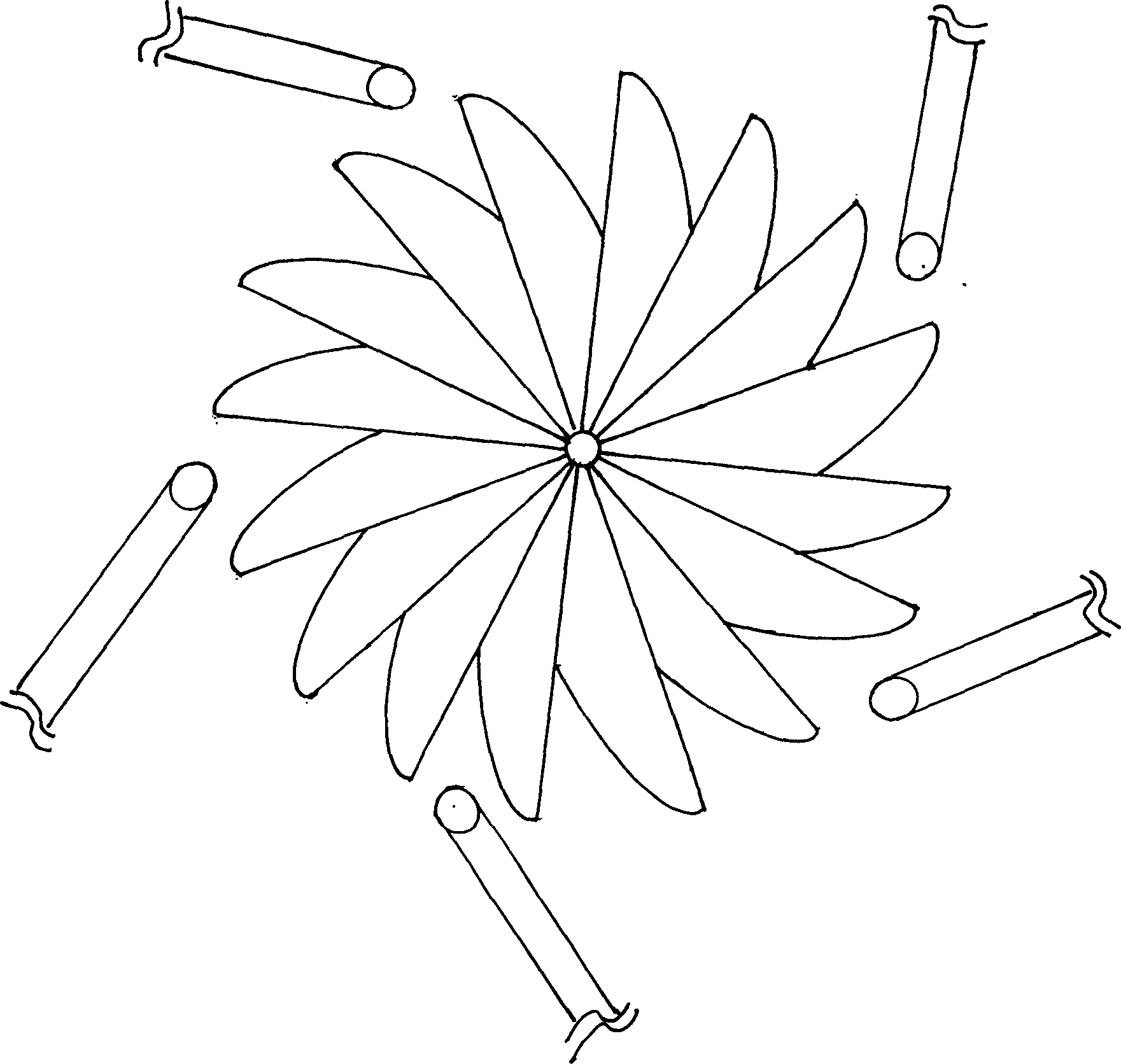
[0010] Such as figure 1 As shown, the wind energy power station uses a plurality of bell mouths 1 or forms a bell mouth array to collect wind energy. The bell mouths are installed in different directions in different places, and each bell mouth is connected to the air guide pipe 2 respectively. In machine room 3, several branch air ducts in the same direction or at the same place can also be aggregated into a total air duct 2′, which is then connected to the machine room of generator 5, and wind energy is combined into more powerful energy. Arranged according to the direction in which the generator impeller 4 rotates ( figure 2 ), and aligned with the generator impeller, the impeller is connected with the generator shaft 6, when the wind energy collected by the bell mouth from all directions is transmitted to the generator set through the air duct and acts on the impeller, the generator impeller rotates, and the impeller drives the engine shaft Spin, the generator works. At...


PUM


Abstract

The invention relates to an energy collection pipe transferring wind energy generator that belongs to wind collection ultra-large wind power generating device. It has at least one bugle-shaped wind collection mouth connecting wind guiding pipe that connect to the sealed machine room and the entrance is aiming at the wind energy generator driving structure or the generator impeller. A chimney type suction ventilation pipe extending to upward is set on the top of the sealed machine room. The invention could omnidirectionally suck wind power and expand the acreage of wind collecting. And the wind energy wasted in wind guiding pipe is low, so the generator works steadily.

Description

Technical field: [0001] The invention relates to a wind-collecting type ultra-large-capacity wind power generating device. Background technique: [0002] Existing wind power plants utilize the principle of windmills, which have low efficiency, and the power generation capacity of a single generator is very limited and difficult to increase because the generator must be installed on a high pedestal. To increase the generating capacity, it is necessary to increase the diameter of the fan blades and increase the number of generators, so the installation range is scattered. Therefore, the equipment investment is high, the maintenance cost is high, the reliability is low, and the power cost of production is high. Invention content: [0003] The purpose of the present invention is to overcome above deficiency and provide a kind of receiving area of ​​increasing wind, quicken the flow velocity of wind, can concentrate the place to install the generator set of high and large capa...

Claims


Application Information

Patent Timeline
Patent Type & Authority Applications(China)
IPC IPC(8): F03D3/04F03D9/25F03D9/34
CPCY02E10/465Y02E10/728Y02E10/74Y02E10/46
Inventor 徐江荧
Owner 徐江荧
Learn More