Voltage control oscillator

A voltage-controlled oscillation and inductor technology, applied in power oscillators, circuits, electrical components, etc., can solve problems such as the reduction of oscillation frequency f

Inactive Publication Date: 2005-09-21
RENESAS ELECTRONICS CORP
View PDF0 Cites 3 Cited by
  • Summary
  • Abstract
  • Description
  • Claims
  • Application Information

AI Technical Summary

Problems solved by technology

Therefore, if Figure 4 As shown in , there is a negative correlation between the voltage (VG-VW) applied to the varactor elements 9, 10 and the oscillation frequency f of the LC-VCO101, and as the voltage (VG-VW) increases, the oscillation frequency lower f

Method used


Image

  • Voltage control oscillator
  • Voltage control oscillator
  • Voltage control oscillator

Examples


Embodiment Construction

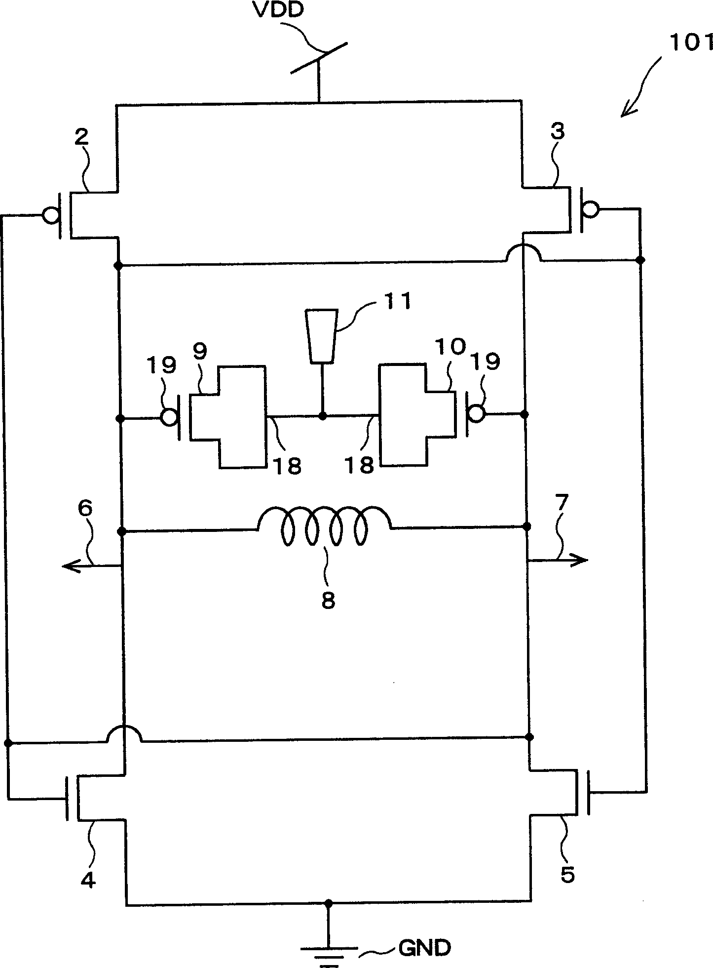
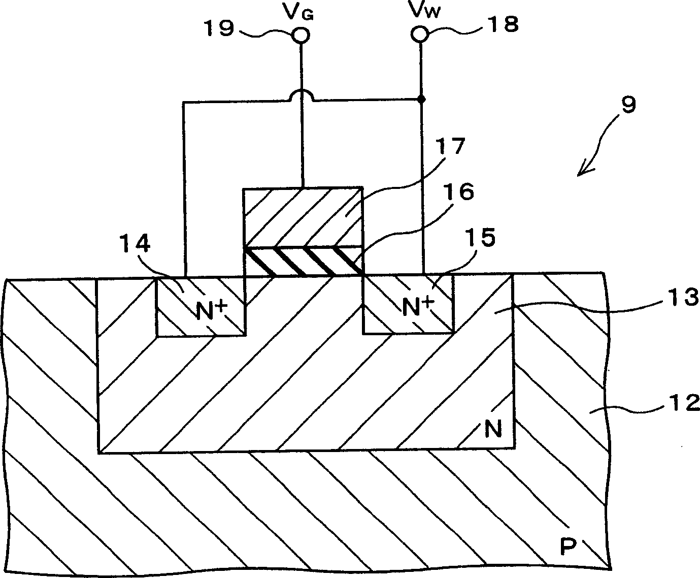
[0044] Hereinafter, embodiments of the present invention will be described in detail with reference to the accompanying drawings. First, a first embodiment of the present invention is described. Figure 6 is a circuit diagram showing the LC-VCO related to this embodiment. Such as Figure 6 As shown, in the LC-VCO 1 of the first embodiment, with figure 1 Compared to the conventional LC-VCO 101 shown in , the connection directions of the varactor elements 9 and 10 are reversed. That is, well terminals 18 of varactor elements 9 and 10 are connected to output terminals 6 and 7 , and gate terminals 19 of varactor elements 9 and 10 are connected to control terminal 11 .

[0045] Except for the above-mentioned structural points, other structural points of the LC-VCO 1 of this embodiment are the same as those of the above-mentioned conventional LC-VCO 101 . That is, the LC-VCO 1 has a resonance section and an amplification section. The resonance section outputs complementary alte...


PUM


Abstract

An LC circuit including an inductor and a pair of varactor elements is provided in an LC-VCO. This LC circuit outputs complementary alternating current signals from a pair of output terminals. The varactor element is formed by providing a gate electrode on an N well. Then, the well terminals of the varactor elements are connected to the respective output terminals, and the gate terminals of the varactor elements are connected to a control terminal. Thereby, as a control voltage to be applied to the control terminal becomes higher, the capacitance of the varactor element increases, and the frequency of the alternating current signal lowers.

Description

technical field [0001] The present invention relates to a voltage controlled oscillator utilizing the resonance of an LC circuit including a varactor element and an inductor, and more particularly, to a varactor including a variable capacitor capable of changing its capacitance according to an applied voltage. A voltage-controlled oscillator with a capacitor diode element. The voltage controlled oscillator according to the present invention can be used as a local oscillator of a phase-locked loop circuit or the like. Background technique [0002] Recently, as a local oscillator (LO) of a phase-locked loop (PLL) circuit for the purpose of frequency multiplication and phase synchronization, a voltage-controlled oscillator (LC-VCO) utilizing resonance of a parallel LC circuit has been adopted. In this LC-VCO, an inductor and a variable capacitor are connected in parallel to each other to form a parallel LC circuit, and by resonance of this parallel LC circuit, an AC signal hav...

Claims


Application Information

Patent Timeline
Patent Type & Authority Applications(China)
IPC IPC(8): H01L29/00H03B5/00H03B5/04H03B5/12
CPCH03B5/1228H03B5/1293H03B5/1212H03B5/1253
Inventor 冈本冬树
Owner RENESAS ELECTRONICS CORP
Why Eureka
Try Eureka