Portable potential difference meter with high resolution ratio

A potentiometer and portable technology, applied in the field of high-resolution portable potentiometers, can solve the problems of unavailability, switch contact resistance and the influence of variation can not be ignored, etc.

Inactive Publication Date: 2005-09-28
骆乃光
View PDF0 Cites 25 Cited by
  • Summary
  • Abstract
  • Description
  • Claims
  • Application Information

AI Technical Summary

Problems solved by technology

[0002] At present, portable potentiometers with a resolution of 0.1μv cannot be purchased on the market, because to achieve a resolution of 0.1μv,

Method used


Image

  • Portable potential difference meter with high resolution ratio
  • Portable potential difference meter with high resolution ratio

Examples


Embodiment Construction

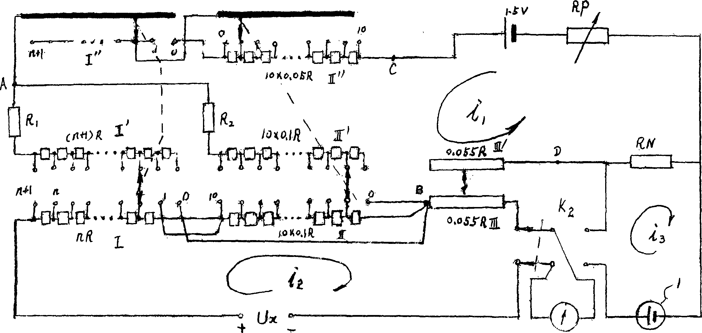
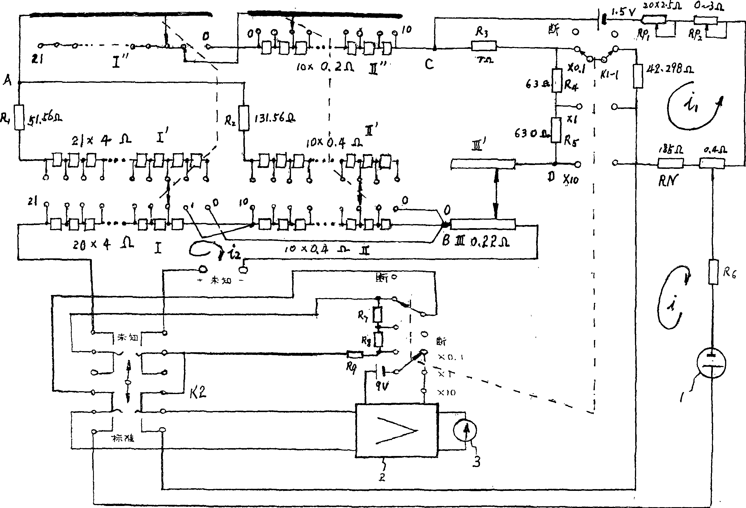
[0016] In the figure, the current flows through the measuring circuit to the set resistance, then to the adjustable resistance and back to the power supply is the working loop i 1 , from the positive pole of the measuring end to the measuring plate I of the first plate, then to the measuring plate II and the measuring wire plate III, through the galvanometer 3 to the negative pole of the measuring end is the measuring circuit i 2 , from the positive pole of the standard battery 1 to the galvanometer 3 and return to the negative pole of the standard resistance through the set resistance is the i of the standard circuit 3 .

[0017] exist figure 1 Among them, the "0" positions of measuring disc I and measuring disc II are directly connected to the starting point of the third measuring slide line, so that when the three discs throw "0", the measuring circuit and the working circuit only meet at the third measuring slide At the starting point of the line, so the zero potential i...


PUM


Abstract

The portable potential difference meter for high resolution measurement of DC voltage consists of work loop, standard loop and measurement loop. Its measurement loop has three measurement discs connected directly with wires, and no switch contact resistance and its variation. The measurement circuit has no influence of thermal potential, so that the portable potential difference meter has resolution as high as 0.1 microvolt.

Description

technical field [0001] The invention relates to an instrument for measuring DC voltage Background technique [0002] At present, portable potentiometers with a resolution of 0.1 μv cannot be purchased on the market, because to achieve a resolution of 0.1 μv, the lead resistance at zero value, the contact thermoelectric potential, the switch contact resistance and the influence of variation cannot be ignored. Contents of the invention [0003] The purpose of the present invention is to design a portable DC potentiometer, which can minimize the influence of zero-value lead wire resistance, make the influence of contact thermoelectric potential negligible, and the switch in the measurement circuit will not introduce variation, so that the resolution of the instrument can be reduced. Up to 0.1μv, while ensuring sufficient range, can have four to five readings. [0004] The present invention is realized through the following technical scheme: the portable potentiometer adopts ...

Claims


Application Information

Patent Timeline
IPC IPC(8): G01R17/20
Inventor 骆乃光
Owner 骆乃光
Why Eureka
Try Eureka