Check patentability & draft patents in minutes with Patsnap Eureka AI!

Variable geometry turbine

A geometry, turbine technology, used in engine manufacturing, combustion engines, gas turbine installations, etc., to solve problems such as overshoot, increased boost pressure, and high intake manifold pressure.

Inactive Publication Date: 2011-06-22
HOLSET ENG CY LTD
View PDF2 Cites 0 Cited by
  • Summary
  • Abstract
  • Description
  • Claims
  • Application Information

AI Technical Summary

Problems solved by technology

However, doing so in a high-efficiency turbine increases boost pressure, resulting in higher intake manifold pressure
This can lead to internal combustion engine cylinder pressures approaching or exceeding permissible limit values

Method used


Image

  • Variable geometry turbine
  • Variable geometry turbine
  • Variable geometry turbine

Examples


Embodiment Construction

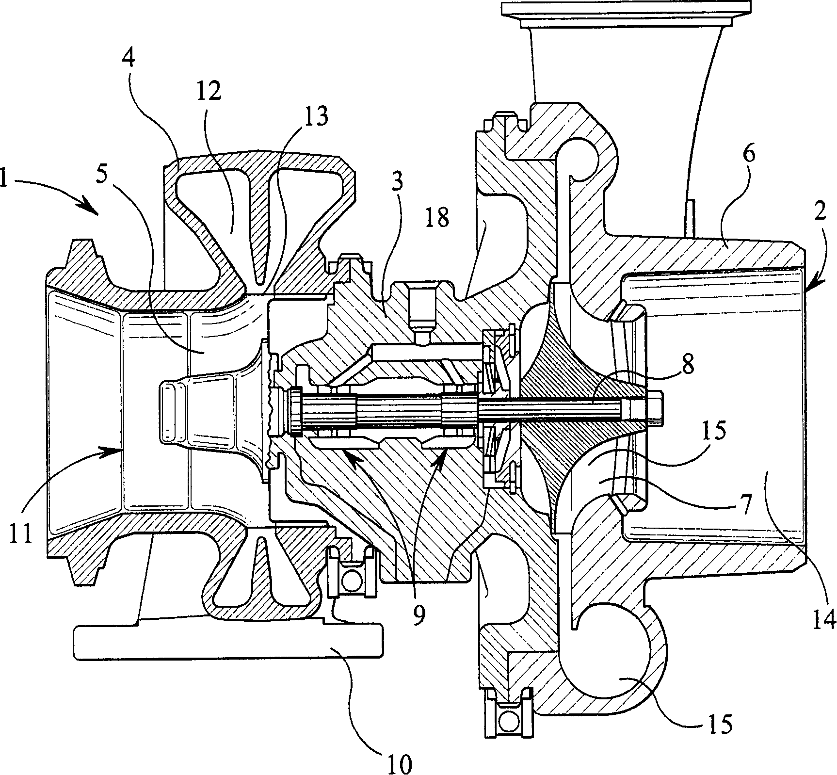
[0025] figure 1 is an axial sectional view of a typical turbocharger with a fixed geometry turbine showing the basic parts of the turbocharger. The turbocharger comprises a turbine 1 connected via a central bearing housing 3 to a compressor 2 . The turbine 1 comprises a turbine housing 4 in which a turbine wheel 5 is accommodated. Similarly, the compressor 2 comprises a compressor housing 6 in which a compressor wheel 7 is placed. The turbine wheel 5 and the compressor wheel 7 are mounted on both ends of a conventional turbine shaft 8 supported by a bearing assembly 9 inside the bearing housing 3 .

[0026] The turbine housing 4 has an exhaust gas inlet 10 and an exhaust gas outlet 11 . Inlet 10 directs incoming exhaust gas into an annular inlet chamber, volute 12 , which surrounds turbine wheel 5 and communicates therewith through a radially extending annular inlet passage 13 . The rotation of the turbine wheel 5 drives the rotation of the compressor wheel 7, which draws ...


PUM


Abstract

A variable geometry turbine comprises a turbine housing (4) defining a turbine chamber within which a turbine wheel (16) is mounted for rotation about a turbine axis (17). The turbine chamber has a radially extending annular inlet (18) defined between facing annular side walls (19,20) of the turbine housing, the annular inlet (18) having an axial width defined between the annular side walls (19,20). An annular array of swing vanes (22) is mounted within the inlet (18), each vane (22) having an axial length (L) extending across the inlet (18) between chordal vane edges lying adjacent respective annular side walls of the inlet (18), and a chordal length (W) defined between leading and trailing vane edges extending across the inlet (18). Means (24,25) are provided for pivoting each vane (22)about a respective pivot axis (23) extending across the inlet to adjust the effective cross-section area of the annular inlet. Each vane is pivotable between a first position in which the area of theinlet (18) is a minimum and a second position in which the area of the inlet (18) is a maximum. At least one of said annular side walls (18,19) is configured so that clearance between the side wall and at least a portion of the adjacent chordal edge of each vane (22) varies in a predetermined manner as the vane moves between positions intermediate the first and second vane positions.

Description

technical field [0001] The invention relates to a variable geometry turbine, in particular to a turbine suitable for a turbocharger of an internal combustion engine. More particularly, the present invention provides beneficial improvements to turbochargers for internal combustion engines with exhaust gas recirculation (EGR) systems. Background technique [0002] A turbine generally consists of a turbine housing and a turbine wheel mounted in a chamber defined by the housing. The turbine chamber is arranged with an annular inlet channel around the turbine wheel and is surrounded by an annular inlet chamber (volute). An outlet passage extends from the turbine chamber, generally along the axis of rotation of the turbine wheel. [0003] Variable geometry turbines with variable geometry inlet channels are known. In a common variable geometry turbine, one wall of the inlet passage is formed by a movable wall member, commonly referred to as a "nozzle ring", whose position relati...

Claims


Application Information

Patent Timeline
IPC IPC(8): F01D17/14F01D17/16F02B37/24F01D5/14F02C6/12
CPCF01D17/165F05D2250/52F05D2220/40F05B2220/40F05D2250/324F02C6/12F02B37/22
Inventor S·加雷特J·帕克
Owner HOLSET ENG CY LTD
Features
  • R&D
  • Intellectual Property
  • Life Sciences
  • Materials
  • Tech Scout
  • Unparalleled Data Quality
  • Higher Quality Content
  • 60% Fewer Hallucinations
Learn More