

Bridging clutch
a clutch and bridging technology, applied in the direction of belts/chains/gearrings, fluid gearings, couplings, etc., can solve the problems of increased friction, excessive stress at the contact area between springs and guides in the openings, and the inability of the turbine wheel to move axially relative to the housing, etc., to achieve stable positioning of the turbine wheel, increase stiffness, and increase rigidity
- Summary
- Abstract
- Description
- Claims
- Application Information
AI Technical Summary
Benefits of technology
Problems solved by technology
Method used
Image

Examples
Embodiment Construction
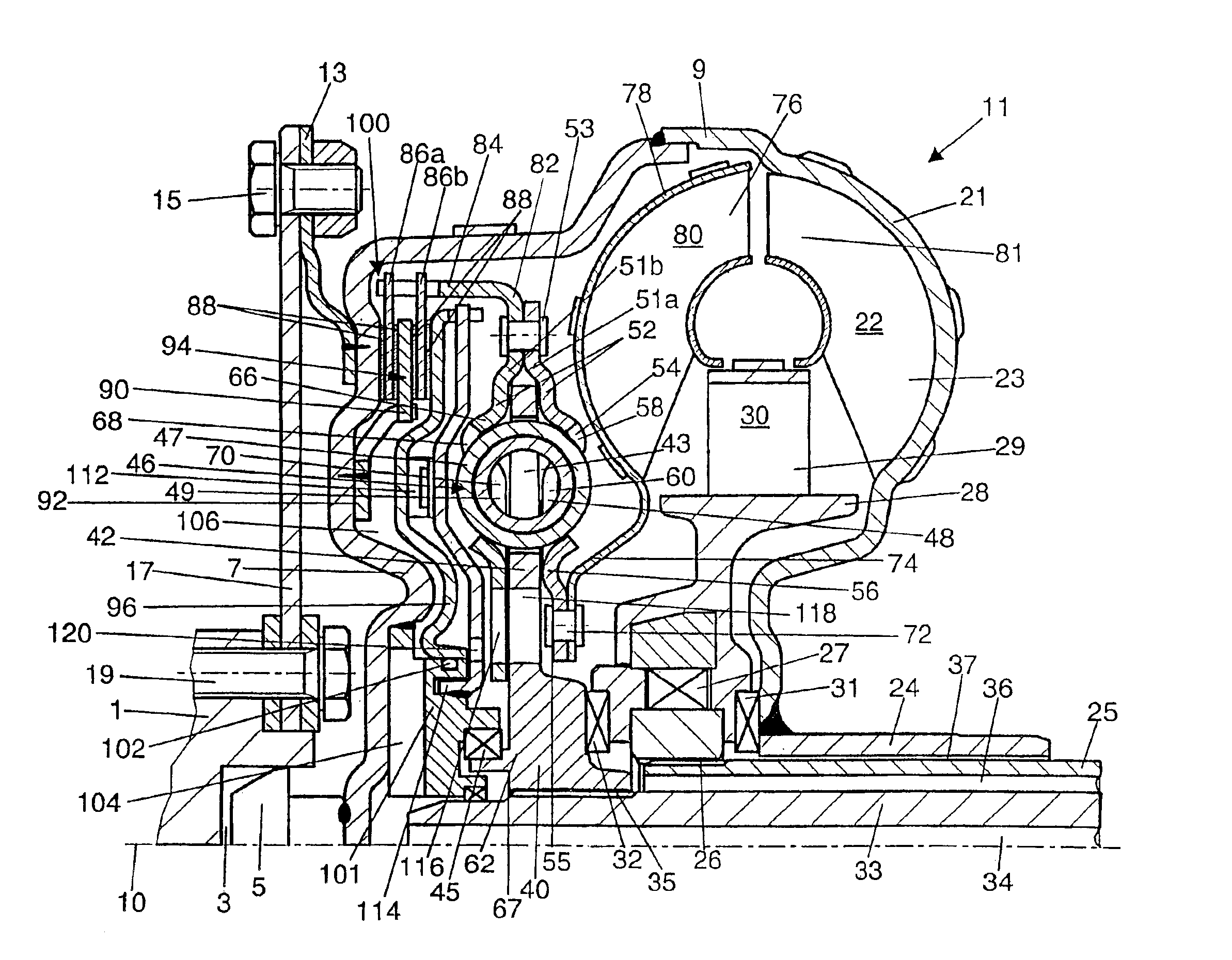
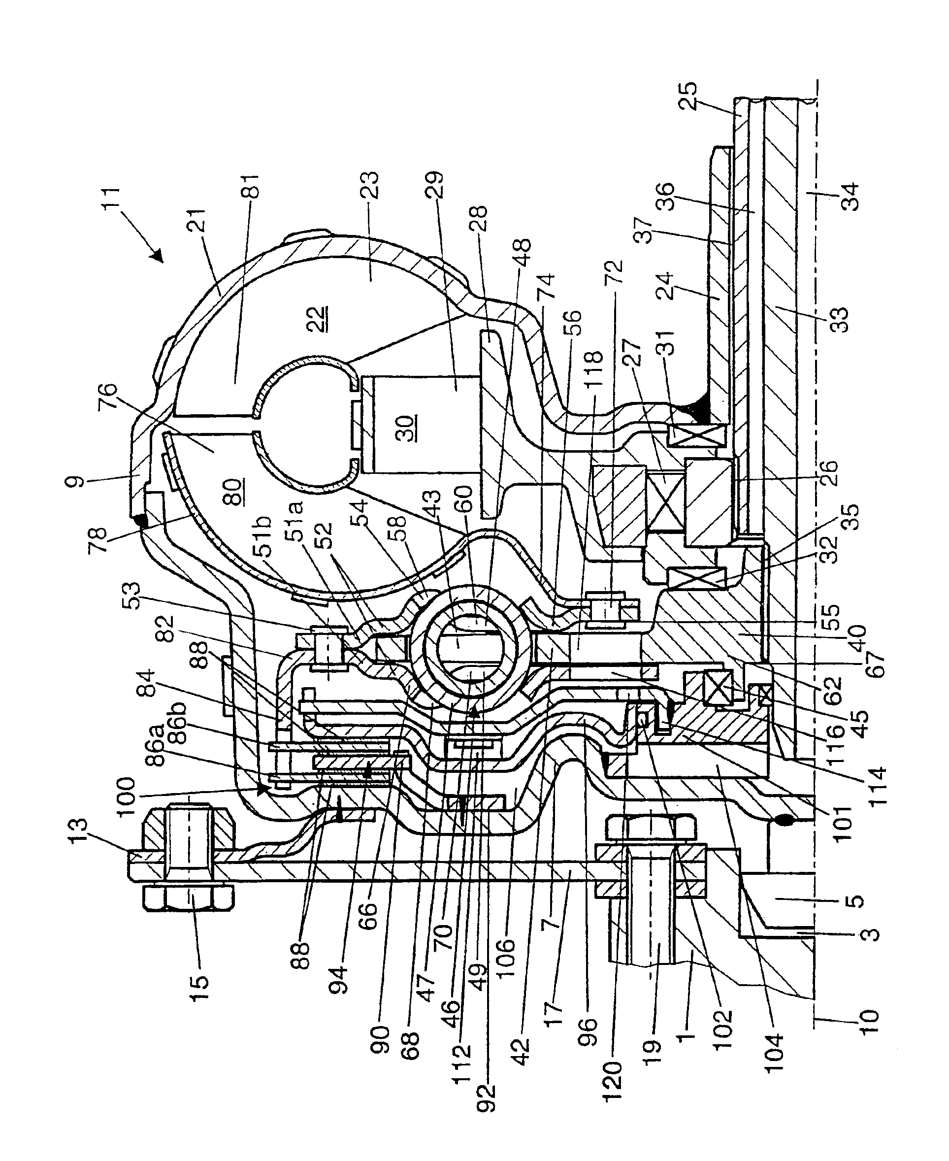
[0016]In a drive shaft 1, formed, for example, by the crankshaft of an internal combustion engine, a central opening 3 is provided to accept a bearing journal 5, which is attached to the converter cover 7 of the housing 9 of a coupling device 11, which is free to rotate around an axis of rotation 10. The Figure shows the coupling device in the form of a hydrodynamic torque converter, but a hydraulic clutch could also be imagined.
[0017]Flanges 13 are attached to the radially outer part of the converter cover; each of these flanges has a screw joint 15, which serves to fasten the coupling device 11 to the radially outer area of a flexplate 17. The radially inner area of the flexplate 17 is fastened in turn by screw joints 19 to the drive shaft 1. The flexplate 17 makes it possible for the coupling device 11 to be connected to the drive shaft with axial elasticity in the known manner.
[0018]The part of the housing 9 facing away from the drive shaft 1 is designed as a pump shell 21, whic...
PUM
 Abstract
Description
Claims
Application Information