Hydrodynamic clutch device

a technology of hydraulic clutch and bridging clutch, which is applied in the direction of rotary clutches, fluid couplings, gearings, etc., can solve the problem that the bridging clutch does not form a sealing point, and achieve the effect of almost completely eliminating the loss of slippage in the area of the bridging clutch

Inactive Publication Date: 2006-06-15
ZF FRIEDRICHSHAFEN AG
View PDF6 Cites 39 Cited by
  • Summary
  • Abstract
  • Description
  • Claims
  • Application Information

AI Technical Summary

Benefits of technology

[0016] It is interesting that, in the inventive clutch device, not only the axial position of the piston of the bridging clutch but also the pressure and filling situation in the hydrodynamic circuit are determined by the two pressure medium lines leading to the sides of the piston. The feed line realized in conventional clutch devices in the area of the freewheel of the stator by thrust washers located on ether side of the stator is thus eliminated. Although these types of thrust washers can also be present in the inventive clutch device, they do not have to accommodate the otherwise conventional flow channels required to supply fluid to the hydrodynamic circuit and are thus able to absorb the axial load exerted on the freewheel with lower pressures per unit surface area.
[0017] As previously explained, the clutch-engaging operation occurs very quickly because of the compact design of...

Problems solved by technology

As a result, the bridging clutch does not form a sealing poi...

Method used


Image

  • Hydrodynamic clutch device
  • Hydrodynamic clutch device
  • Hydrodynamic clutch device

Examples


Embodiment Construction

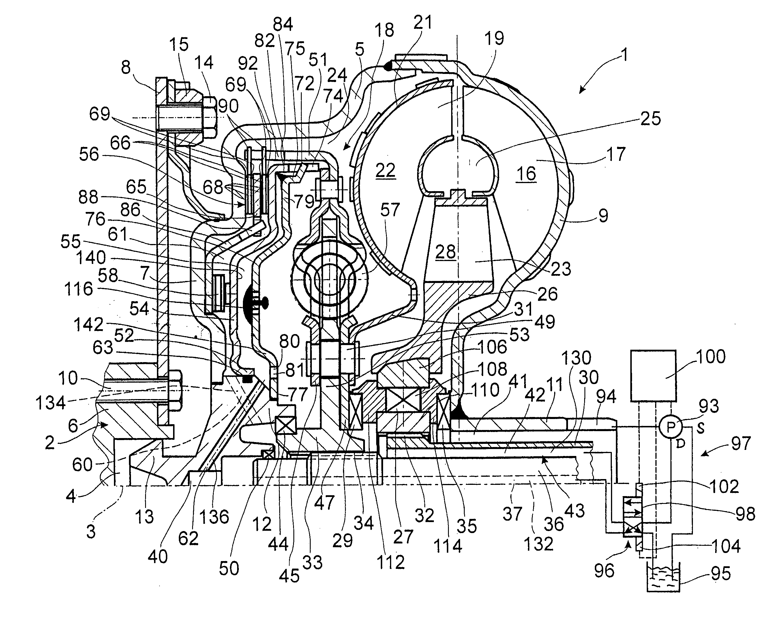
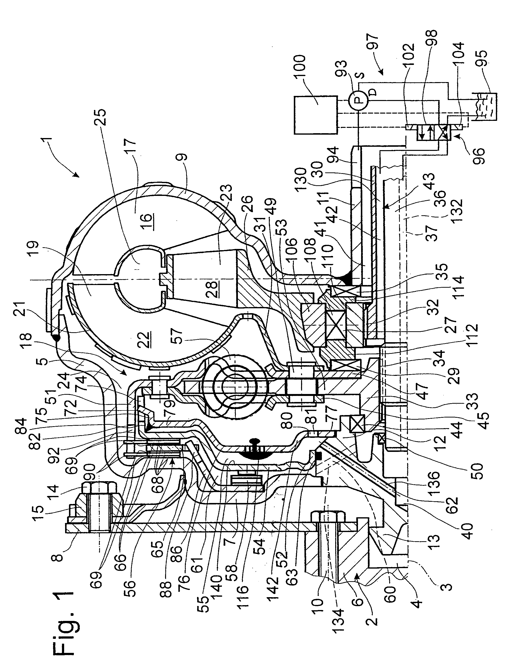
[0023]FIG. 1 shows a hydrodynamic clutch device 1 in the form of a hydrodynamic torque converter, which is able to rotate around an axis of rotation 3. The hydrodynamic torque converter has a clutch housing 5. On the side of the housing facing a drive 2, such as an internal combustion engine with a crankshaft 6, the housing has a cover 7, which is permanently connected to a pump wheel shell 9. This merges with a pump wheel hub 11 in the radially inner area.

[0024] To return to the housing cover 7, this cover has, in the radially inner area, a bearing journal hub 12 carrying a bearing journal 13. The bearing journal 13 is mounted in a recess 4 in the crankshaft 6 to center the clutch housing 5 on the drive side. The housing cover 7 also has a fastening mount 15, which serves to attach the clutch housing 5 to the crankshaft 6 by way of a flexplate 8, namely, by means of fastening elements 14, preferably in the form of bolts screws. The flexplate 8 itself is attached by fastening eleme...


PUM


Abstract

A hydrodynamic clutch device includes a clutch housing connected to a drive, a pump wheel connected to the clutch housing, and a turbine wheel connected to a takeoff, the turbine wheel and the pump wheel forming a hydrodynamic circuit. A bridging clutch which is essentially surrounded by the hydrodynamic circuit includes a piston and at least one friction surface which can be acted on by the piston to connect the drive to the takeoff independently of the hydrodynamic circuit, the piston having one surface facing the hydrodynamic circuit and an opposite surface facing a pressure space. A pressure circuit includes a first pressure medium line to supply the hydrodynamic circuit with clutch fluid and a second pressure medium line to supply the pressure space with clutch fluid. A seal at least reduces the exchange of fluid between the hydrodynamic circuit and the pressure space, and a throttle allows a defined exchange of fluid between the hydrodynamic circuit and the pressure space.

Description

BACKGROUND OF THE INVENTION [0001] 1. Field of the Invention [0002] The invention pertains to a hydrodynamic clutch device of the type having a clutch housing connected to a drive; a pump wheel connected to the clutch housing, the pump wheel having a hub; a turbine wheel connected to a takeoff, the turbine wheel and the pump wheel forming a hydrodynamic circuit; a bridging clutch having a piston and a friction surface which can be acted on by the piston to connect the drive to the takeoff independently of the hydrodynamic circuit, the piston having one surface facing the friction surface and an opposite surface; a pressure space for exerting fluid pressure on the piston; and a pressure circuit including a first pressure medium line to supply the hydrodynamic circuit with clutch fluid and a second pressure medium line to supply the pressure space with clutch fluid. [0003] 2. Description of the Related Art [0004] U.S. Pat. No. 5,575,363 describes a hydrodynamic clutch device designed ...

Claims


Application Information

Patent Timeline
IPC IPC(8): F16H45/02
CPCF16H45/02F16H61/14F16H2045/021F16H2045/0284F16H2045/0289F16H57/0473
Inventor ACKERMANN, JURGEN
Owner ZF FRIEDRICHSHAFEN AG
Why Eureka
Try Eureka