Simplified variable geometry turbocharger with sliding gate and multiple volutes

a variable geometry, turbocharger technology, applied in the direction of machines/engines, stators, liquid fuel engines, etc., can solve the problems of limiting the boost level of the engine, the critical pressure ratio at which the valve opens is detrimentally affected, and the turbine power control characteristics are rudimentary and coarse. the effect of low cos

Active Publication Date: 2010-10-21
BORGWARNER INC
View PDF11 Cites 38 Cited by
  • Summary
  • Abstract
  • Description
  • Claims
  • Application Information

AI Technical Summary

Benefits of technology

[0030]The present invention accomplishes the above mentioned objectives and provides a simplified, low cost, turbine flow controlling device by designing a turbocharger to use a sliding gate, with a discreetly positioning actuator to co

Problems solved by technology

These requirements often result in compromises such as architectural requirements outside of the turbine housing, method of location and mounting of the turbine housing to the bearing housing, and the transition from slice “A” to the turbine foot (51) result in turbine housing volutes of rectangular or triangular section, as well as in circular, or combinations of all shapes.
The function of the wastegate valve, in this manner, is to cut the top off the full load boost curve, thus limiting the boost level to the engine.
While a wastegate can be used to limit boost levels, its turbine power control characteristics are rudimentary and coarse.
If the wastegated turbocharger has a “dumb” actuator, which operates on a pressure or vacuum signal only, and is operated at altitude, then the critical pressure ratio

Method used


Image

  • Simplified variable geometry turbocharger with sliding gate and multiple volutes
  • Simplified variable geometry turbocharger with sliding gate and multiple volutes
  • Simplified variable geometry turbocharger with sliding gate and multiple volutes

Examples


first embodiment

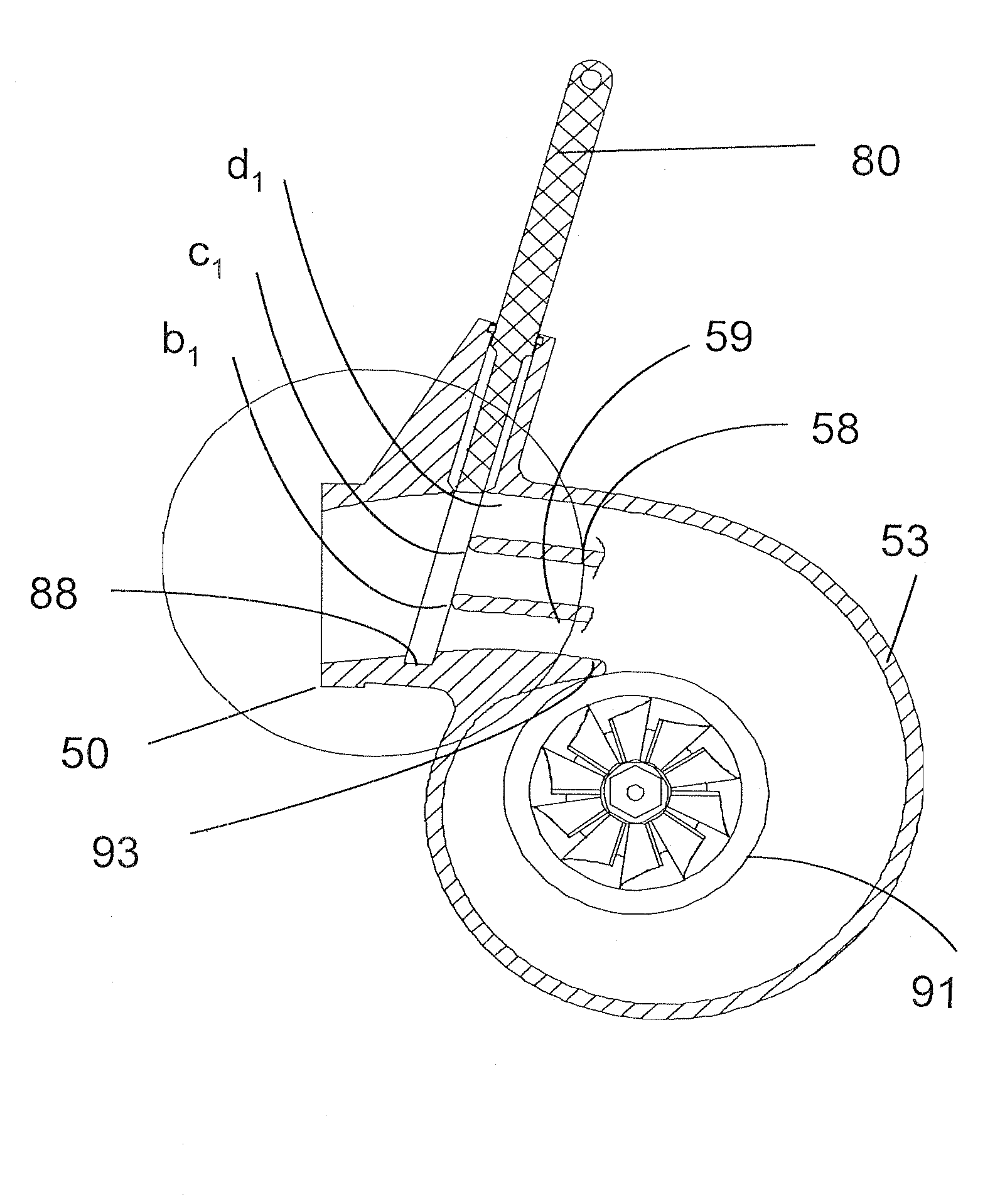
[0051]The turbine housing component of the present invention consists of a plurality (greater than two) of volutes configured such that the entry to the multiple volutes is near the foot (51) and the exits of each volute are arranged around the base circle of the turbine housing. The volutes can be co-planar, or the volutes can cross over each other. What is important is that the volutes cumulatively deliver exhaust air to the circumference of the turbine wheel, terminating at a distance greater than or equal to a diameter of 106% the turbine wheel diameter, in an adjacent configuration.

[0052]In the exemplary first embodiment of the invention, as seen in FIGS. 12A and 12B, the turbine housing has an outer volute bound outwardly by the inner side (53) of the outer wall of the turbine housing. The inner wall of the outer volute is the outside of the first transverse divider wall (58). The “Z” axis walls are bound by walls close to the side walls which would exist in a typical turbine ...

third embodiment

[0061]In the invention, as depicted in FIGS. 15A and 15B, the flow of exhaust gas to the turbine wheel (70) is controlled by the rotation of a pivoting transverse divider wall (27) which is driven by an actuator driving an actuator rod (14) through a clevis (24). A clevis pin (25) transmits the actuator drive though an actuation arm (73), which in turn rotates and actuator shaft (72) about an axis (30).

[0062]The pivoting transverse divider wall (27) has a leading edge (28) and a trailing edge (29) and rotates about the axis (30) of the actuator shaft (72). For the sake of clarity the extreme positions of the actuation arm (73) are marked as “A” and “B”. In position “B” the pivoting transverse divider wall (27) has its leading edge (28) close to the center of the volute cross-sectional area, thus effectively directly the incoming flow of exhaust gas both under and over the transverse divider wall. This splitting of the exhaust flow forces the gas on the outside of the transverse divi...


PUM


Abstract

A simplified, low cost, turbine flow controlling device, using a sliding gate, with an actuator to control exhaust flow to multiple volutes, which volutes have perforated transverse divider walls. By moving the sliding gate (80) from a closed position (88) through a displacement of “a” to the next position b1; and then from position b1 through a displacement of “b” to the next position c1, each a discreet movement, by a simple actuator, an increasing number of volutes are opened for flow from the exhaust manifold, via the volutes with perforated transverse divider walls, to the turbine wheel, without the attenuation of pulse energy usually seen in VTGs, at a cost lower than that of a VTG.

Description

FIELD OF THE INVENTION[0001]This invention is directed to the design of a low cost turbine flow control device capable of maintaining exhaust gas velocity and pulse energy. The low cost turbocharger is matched to low flow regimes to provide optimized turbo (and thus engine) transient response for low flow while being capable of delivering the high flows demanded by the engine in other than low flow conditions, in the same, cost-effective turbocharger.BACKGROUND OF THE INVENTION[0002]Turbochargers are a type of forced induction system. They deliver air, at greater density than would be possible in the normally aspirated configuration, to the engine intake, allowing more fuel to be combusted, thus boosting the engine's horsepower without significantly increasing engine weight. This can enable the use of a smaller turbocharged engine, replacing a normally aspirated engine of a larger physical size, thus reducing the mass and aerodynamic frontal area of the vehicle.[0003]Turbochargers (...

Claims


Application Information

Patent Timeline
IPC IPC(8): F04D29/46
CPCF01D17/141F01D9/026
Inventor HENDERSON, KURTIS E.CHANDRAMOHANAN, RAJMOHAN
Owner BORGWARNER INC
Why Eureka
Try Eureka