
Turbocharger with variable nozzle

a variable nozzle and turbocharger technology, which is applied in the direction of liquid fuel engines, machines/engines, reaction engines, etc., can solve the problems of not particularly pointed out, difficult to quickly obtain a turbo effect, and hardly work of the turbocharger, and achieve the effect of suppressing the heating of the radially expanded portion

Active Publication Date: 2007-08-02
IHI CORP
View PDF20 Cites 38 Cited by
  • Summary
  • Abstract
  • Description
  • Claims
  • Application Information

AI Technical Summary

Benefits of technology

[0017]and a heat shield plate is provided between the variable nozzle mechanism and the radially expanded portion for preventing a heat transmission between the variable nozzle mechanism and the radially expanded portion.
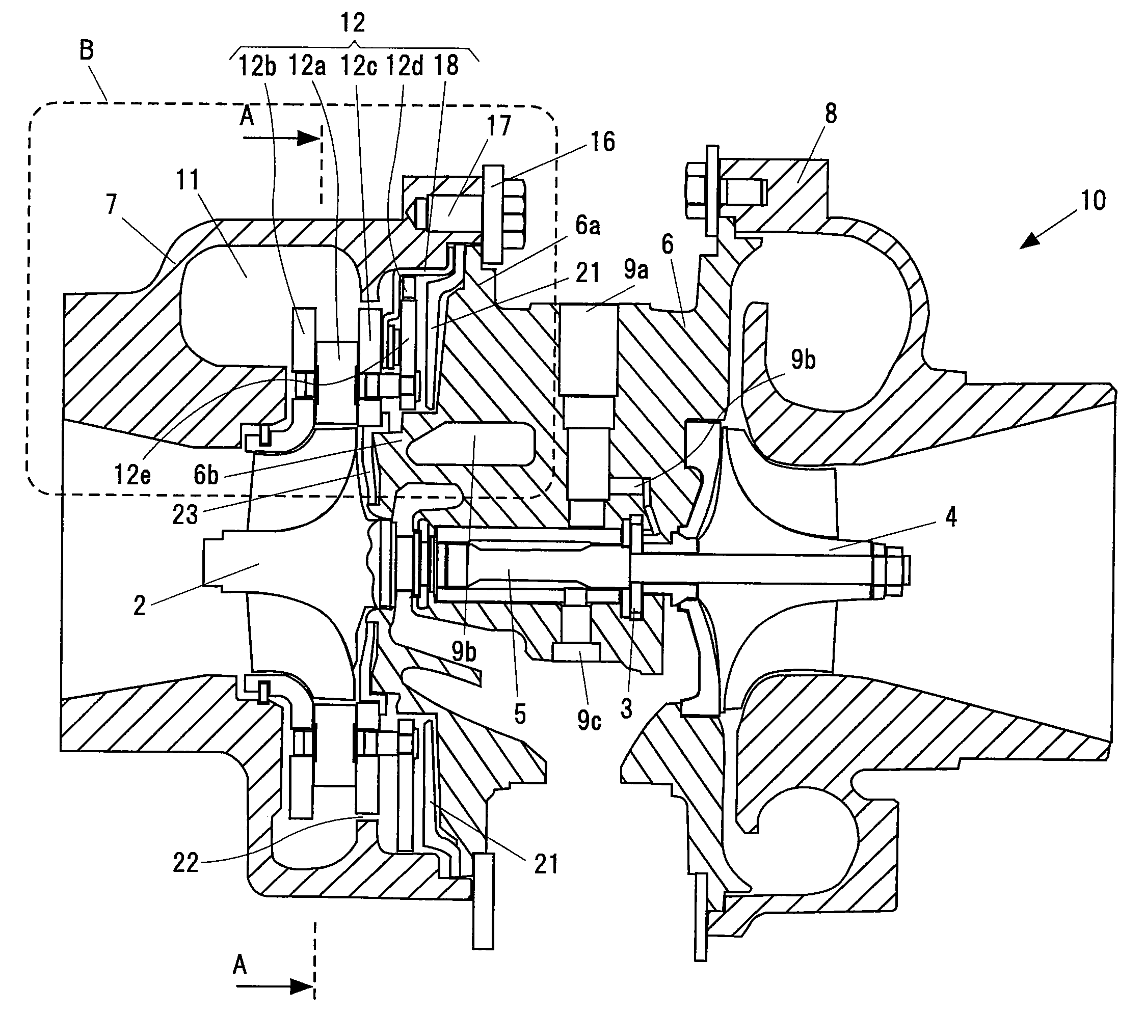
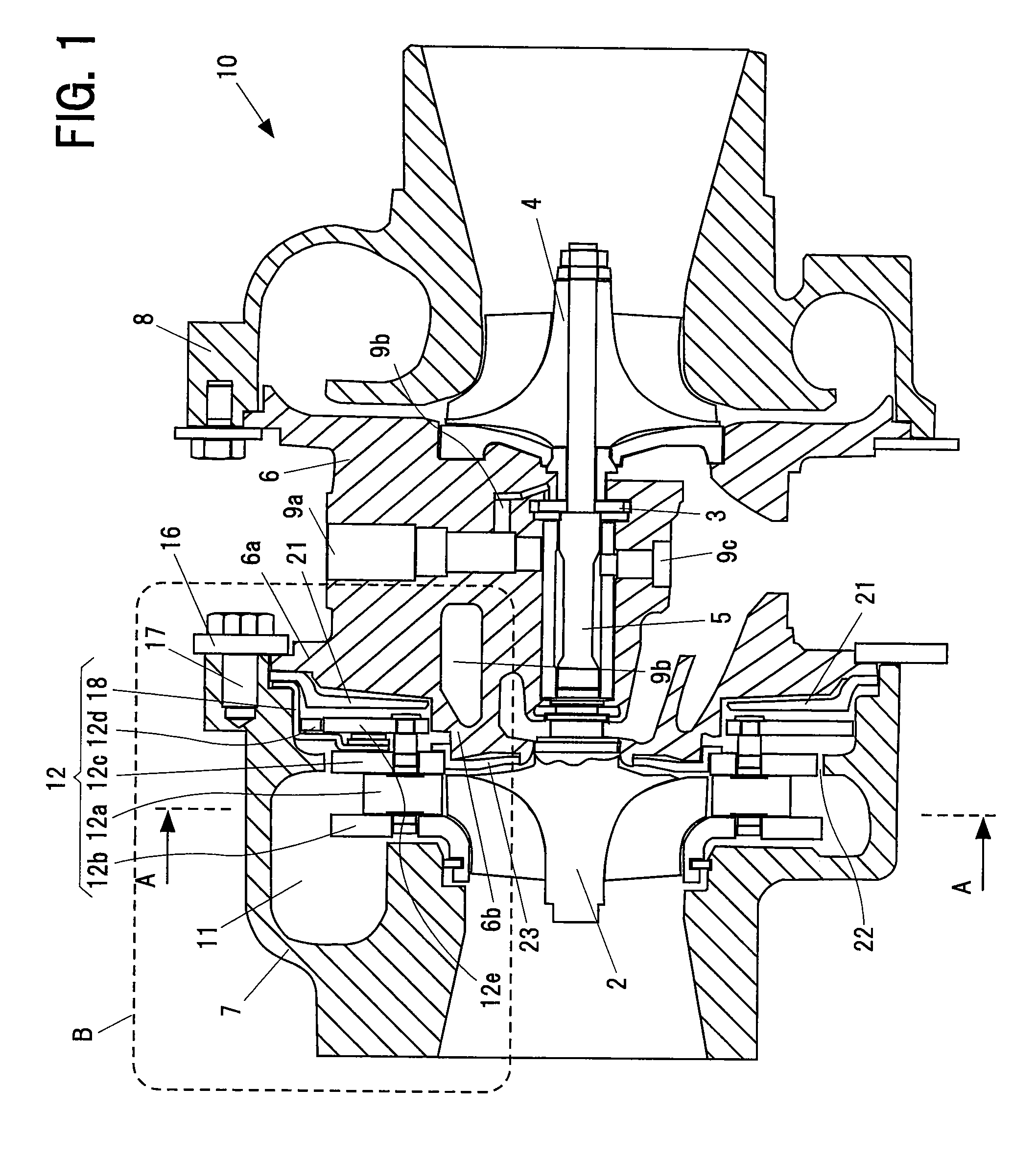
[0018]As for a turbocharger with the variable nozzle, since the variable nozzle mechanism is accommodated between the turbine housing and the bearing housing, the bearing housing has the radially expanded portion extending in the radial direction to be coupled to the radial-direction outer side portion of the turbine housing. Accordingly, the bearing housing is enlarged in size in comparison with the conventional one, and a heat capacity thereof becomes enlarged at that degree. In a hydraulic cooling, it is impossible to sufficiently cool the heat of the radially expanded portion in the bearing housing. However, in the turbocharger with the variable nozzle in accordance with the present invention mentioned above, since the heat shield plate is provided between the variable nozzle mechanism and the radially expanded portion of the bearing housing, in the outer side in the radial direction, it is possible to prevent the heat from being transmitted to the radially expanded portion from the turbine side. In other words, the heat shield plate is provide by providing a space between the variable nozzle mechanism and the radially expanded portion so that radiant heat from high-temperature components at the turbine side can be prevented from transmitting directly to the bearing housing, suppressing a temperature increase in the bearing housing. Accordingly, it is possible to suppress the heating of the radially expanded portion in the bearing housing. As a result, even when the engine stops and supply of the pressure oil for cooling the bearing housing stops, it is possible to maintain the temperature of the thrust bearing or the like equal to or less than the critical temperature.
[0020]Accordingly, since the heat shield plate can be fixed by only holding the heat shield plate between the turbine housing and the bearing housing, at a time of assembling the turbocharger, it is easy to fix the heat shield plate.
[0022]Accordingly, even if the heat transmission from the turbine side to the radially expanded portion of the bearing housing is generated through the contact portion existing in the radial-direction outer end portion of the heat shield plate, the other portion of the heat shield plate does not contact with the turbine housing and the bearing housing, so that it is possible to minimize an amount of heat transmission from the turbine side to the radially expanded portion through this non-contact portion. Therefore, it is possible to further effectively prevent the heat transmission from the turbine side to the radially expanded portion.
[0025]In the present invention mentioned above, since the heat shield plate is provided between the variable nozzle mechanism and the radially expanded portion of the bearing housing, it is possible to prevent the heat transmission from the turbine side to the radially expanded portion. Accordingly, it is possible to suppress the heating of the radially expanded portion in the bearing housing. As a result, even when the engine stops and supply of the pressure oil for cooling the bearing housing stops, it is possible to maintain the temperature of the thrust bearing or the like equal to or less than the critical temperature.

Problems solved by technology

In the turbocharger, at the time of low speed revolution of the engine, the turbine hardly works due to a low exhaust flow rate.
Accordingly, in the engine capable of operating at a high speed revolution, it takes a long time until the turbine efficiently rotates, so that it is impossible to quickly obtain a turbo effect.
However, in the turbocharger with the variable nozzle, there is a problem that a temperature of a thrust bearing provided in a compressor side of a bearing housing gets over a critical temperature 250° C. so as to be increased to about 300° C. due to a heat transmission (a heat soak) from a turbine side of the bearing housing to the compressor side, at a time when the engine stops and a pressure oil cooling the bearing housing stops.
Meanwhile, the problem mentioned above is not particularly pointed out in the turbocharger with no variable nozzle.

Method used


Image

  • Turbocharger with variable nozzle
  • Turbocharger with variable nozzle
  • Turbocharger with variable nozzle

Examples


Embodiment Construction

[0030]The description will be given of a preferable embodiment in accordance with the present invention with reference to the accompanying drawings. Meanwhile, the same reference numerals are attached to common portions in each of the drawings, and the repeated description will be omitted.

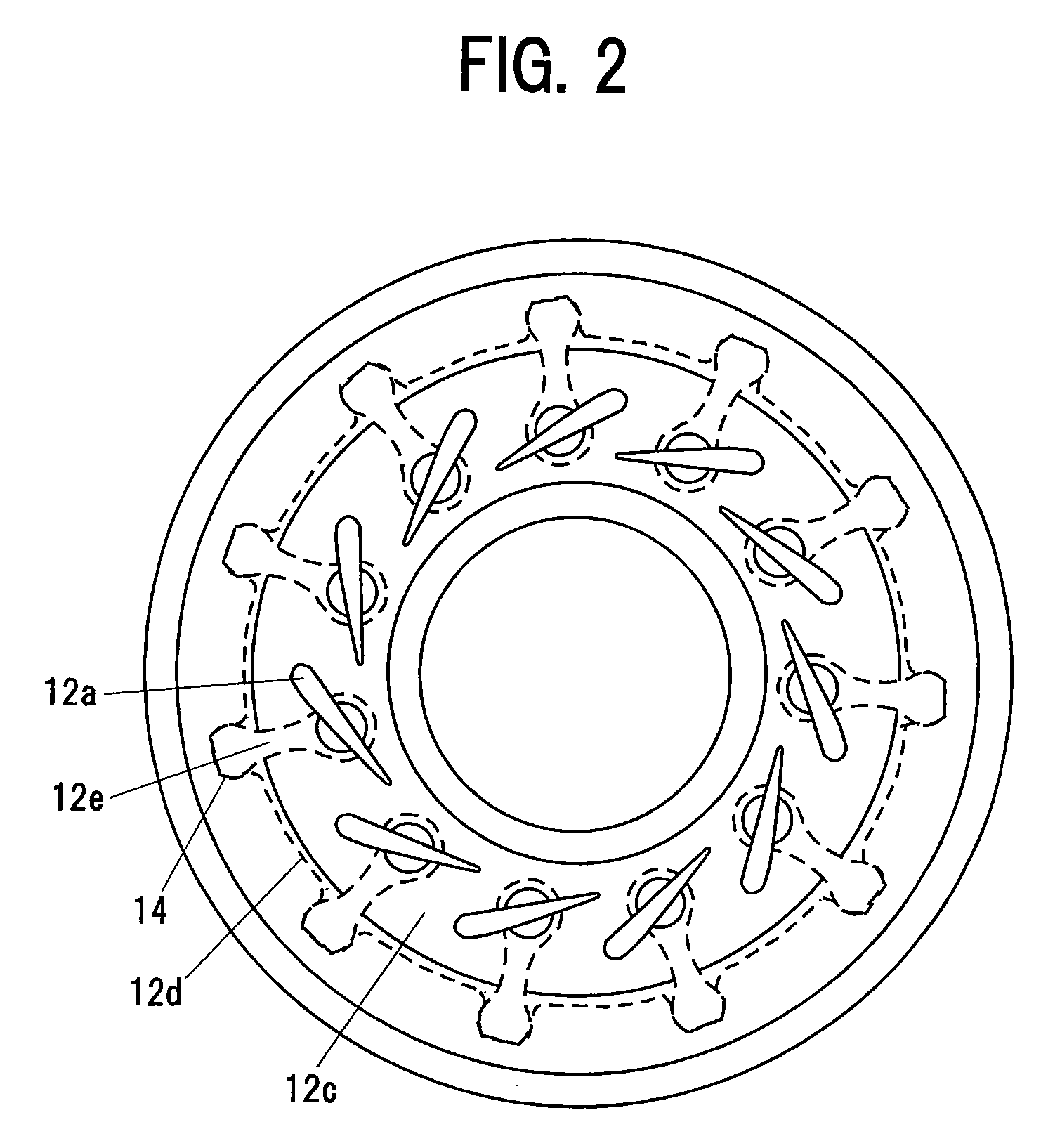
[0031]FIG. 1 is a cross sectional view in an axial direction of a turbocharger 10 with a variable nozzle showing an embodiment in accordance with the present invention. FIG. 2 is a view along a line A-A in FIG. 1, and shows a variable nozzle mechanism 12 adjusting a flow rate of an exhaust gas from an engine to a turbine.

[0032]A turbocharger 10 with a variable nozzle shown in FIG. 1 is provided with a turbine impeller 2 rotationally driven by the exhaust gas from the engine, a compressor impeller 4 rotationally driven by a driving force of the turbine so as to supply a compressed air to the engine, a shaft 5 coupling the turbine impeller 2 and the compressor impeller 4, a bearing housing 6 rotatabl...


PUM


Abstract

A turbocharger with a variable nozzle has a turbine impeller, a compressor impeller, a shaft coupling the turbine impeller and the compressor impeller, a bearing housing rotatably supporting the shaft, and a turbine housing accommodating the turbine impeller. The turbocharger further includes a variable nozzle mechanism, provided in a compressor impeller side in a radial-direction outer side of the turbine impeller, for adjusting a flow rate of an exhaust gas directed to the turbine impeller. The bearing housing has a radially expanded portion that extends to a radial-direction outer side to be coupled to the turbine housing at a radial-direction outer side portion thereof such that the variable nozzle mechanism is accommodated between the turbine housing and the radially expanded portion. Between the variable nozzle mechanism and the radially expanded portion, a heat shield plate is provided for preventing a heat transmission between them.

Description

BACKGROUND OF THE INVENTION[0001]1. Technical Field of the Invention[0002]The present invention relates to a turbocharger with a variable nozzle, and more particularly to a turbo charger with a variable nozzle having a mechanism capable of suppressing a temperature increase of a compressor side thrust bearing or the like.[0003]2. Description of the Related Art[0004]A turbocharger is a supercharger used for a high output of an engine, for example, for a motor vehicle. In the turbocharger, a compressed air is supplied to the engine from a compressor by rotating a turbine impeller by exhaust energy of the engine, and rotating a compressor impeller by an output of the turbine. Accordingly, it is possible to achieve a supercharging state over a natural air supply in the engine.[0005]In the turbocharger, at the time of low speed revolution of the engine, the turbine hardly works due to a low exhaust flow rate. Accordingly, in the engine capable of operating at a high speed revolution, it ...

Claims


Application Information

Patent Timeline
IPC IPC(8): F02B33/44
CPCF01D17/165F05D2260/231F05D2220/40F01D25/162F02B37/22F02B37/12F01D17/16F02D9/02
Inventor KOBAYASHI, TAKAHIRO
Owner IHI CORP
Learn More