Composite casing of travelling-wave tube

A composite tube shell and traveling wave tube technology, which is applied in the manufacture of tube shells/containers, ships or lead-in wires of transit-time electron tubes, etc.

Inactive Publication Date: 2005-10-12
INST OF ELECTRONICS CHINESE ACAD OF SCI
View PDF0 Cites 7 Cited by
  • Summary
  • Abstract
  • Description
  • Claims
  • Application Information

AI Technical Summary

Problems solved by technology

People have also considered using dispersed copper to make the shell of the traveling wave tube, but the domestically produced dispersed copper cannot guarantee vacuum airtightness.
In ...

Method used


Image

  • Composite casing of travelling-wave tube
  • Composite casing of travelling-wave tube
  • Composite casing of travelling-wave tube

Examples


Embodiment Construction

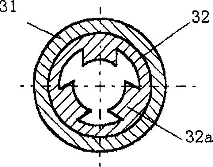
[0023] The novel composite shell of the present invention for traveling wave tubes such as image 3 shown. The number 31 among the figure is the outer shell, and the number 32 is the inner shell. Both the outer shell 31 and the inner shell 32 are tubular, and the lengths of the two are the same. The inner wall surface of the tube shell 31 is fixedly connected to the outer peripheral surface of the inner tube shell 32 . The outer tube shell 31 is made of Monel, non-magnetic stainless steel and other materials, which not only has sufficient mechanical strength, but also ensures vacuum airtightness. The inner tube shell 32 is made of oxygen-free copper with excellent electrical conductivity, and the inner tube shell 32 can be cut into various shapes by wire cutting, for example, the inner tube shell 32 can have fins 32a. In addition, the outer shell 31 and the inner tube 32 are welded in a proper manner.

[0024] image 3 Shown is the manufacturing process of the novel compo...


PUM


Abstract

The invention consists of outer tube case and inner tube case, which all are shape tube and have same length. The inner diameter of outer tube case matches the outer diameter of inner tube case, and inner tuber case is housed in outer tube case. The inwall of outer tube case makes rigid coupling with out wall of inner tube case.

Description

technical field [0001] The invention relates to the technical field of electronic vacuum tubes, and relates to a novel composite shell for traveling wave tubes. Background technique [0002] Traveling wave tube is a high-power and wide-band high-power electric vacuum device, which is widely used in radar, navigation, electronic interference and satellite communication and other fields, and its function is to generate or amplify high-power microwave or millimeter wave. The tube shell is the container of the TWT interaction area and the frame of the slow wave structure of the TWT. Its performance directly affects the efficiency of the TWT interaction and has a direct and important impact on the overall performance of the TWT. [0003] The traveling wave tube is an electric vacuum device. The tube shell must first have good vacuum tightness; secondly, it must have a certain mechanical strength so that it will not be deformed and damaged during manufacturing and application; in ...

Claims


Application Information

Patent Timeline
IPC IPC(8): H01J9/24H01J23/12
Inventor 李海强宋培德戴志浩
Owner INST OF ELECTRONICS CHINESE ACAD OF SCI
Why Eureka
Try Eureka