Receiver circuit for radio clock and method for operating receiving circuit

A receiving circuit, radio technology, applied in the field of filter circuit, radio clock receiving circuit, can solve the problem of small battery life battery and so on

Active Publication Date: 2005-10-19
ATMEL GERMANY +1
View PDF4 Cites 3 Cited by
  • Summary
  • Abstract
  • Description
  • Claims
  • Application Information

AI Technical Summary

Problems solved by technology

This "worst-case" design of the system results in either the battery having on

Method used


Image

  • Receiver circuit for radio clock and method for operating receiving circuit
  • Receiver circuit for radio clock and method for operating receiving circuit
  • Receiver circuit for radio clock and method for operating receiving circuit

Examples


Embodiment Construction

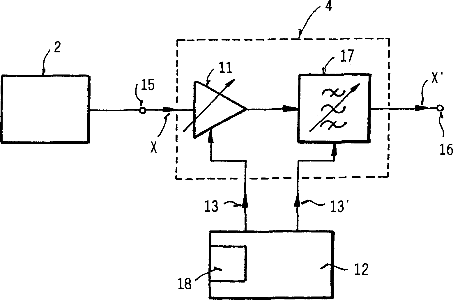
[0052] image 3 A first variant of the inventive radio timepiece with adjustable magnification is shown by a block circuit diagram.

[0053] A radio timepiece indicated by reference numeral 1 has one (or more) antennas 2 for receiving a time stamp signal X transmitted by a time stamp signal transmitter 3 . The radio timepiece 1 also has a receiving circuit 4 for receiving the time mark signal X transmitted by the time mark signal transmitter 3 and received by the antenna 2 , the input terminal of the receiving circuit is connected to the antenna 2 . The receiving circuit 4 typically includes one or more filters, such as band-pass filters, a detection circuit and an amplification circuit for filtering, detecting and amplifying the received time scale signal X. In particular the following Figures 4 to 6 The structure and function of such a receiving circuit 4 are described in more detail.

[0054] In addition, a decoding device 5 is provided, which is connected downstream of ...


PUM


Abstract

The circuit (4) has a reception input to receive a time signal carrying encoded time information. An amplifier circuit amplifies the signal to produce an amplified time signal, and includes an adjustable amplifier with a variable amplification factor that is adjusted depending on frequency of the received time signal. An adjustable bandpass filter filters the amplified time signal to produce a filtered amplified time signal. Independent claims are also included for the following: (A) a radio-controlled clock including a receiver circuit (B) a method of acquiring time information.

Description

technical field [0001] The invention relates to a radio watch receiver circuit for receiving time stamp signals containing time information in coded form transmitted by different time stamp signal transmitters, which has an amplifier circuit for amplifying the received time stamp signal, and There is a filter circuit for filtering the received time scale signal. The invention also relates to a method for obtaining time information from a transmitted time stamp signal by means of such a receiving circuit and to a radio timepiece having such a receiving circuit. Background technique [0002] The radio-controlled transmission of the time information takes place by means of so-called time stamp signals (Zeitzeichensignales), which are transmitted by corresponding transmitters—hereinafter simply referred to as time stamp signal transmitters (Zeitzeichensender). A time stamp signal is to be understood as a short-duration transmitted signal, which is assigned the task of transmitt...

Claims


Application Information

Patent Timeline
IPC IPC(8): G04G5/00G04R20/10H04B1/16
CPCG04R20/10G04G5/002
Inventor 约阿希姆·屈恩勒罗兰·波洛尼奥汉斯-约阿希姆·赛勒
Owner ATMEL GERMANY
Why Eureka
Try Eureka