Negative pulse charging emergency power supply

An emergency power supply and negative pulse technology, applied in the field of power supply, can solve the problems of large initial charging current and fast decay

Inactive Publication Date: 2005-10-26
周熙文
View PDF0 Cites 12 Cited by
  • Summary
  • Abstract
  • Description
  • Claims
  • Application Information

AI Technical Summary

Problems solved by technology

Depend on Figure 8 It can be seen that the initial

Method used


Image

  • Negative pulse charging emergency power supply
  • Negative pulse charging emergency power supply
  • Negative pulse charging emergency power supply

Examples


Embodiment Construction

[0028] The present invention will be further described below in conjunction with the embodiments and accompanying drawings.

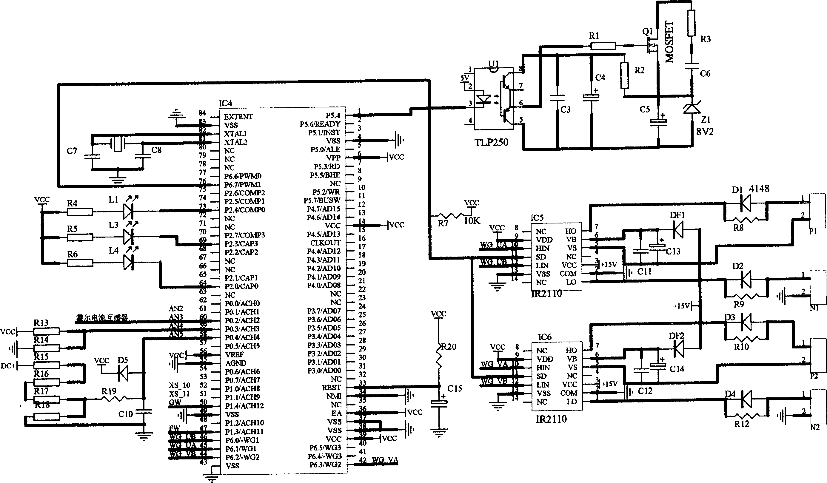
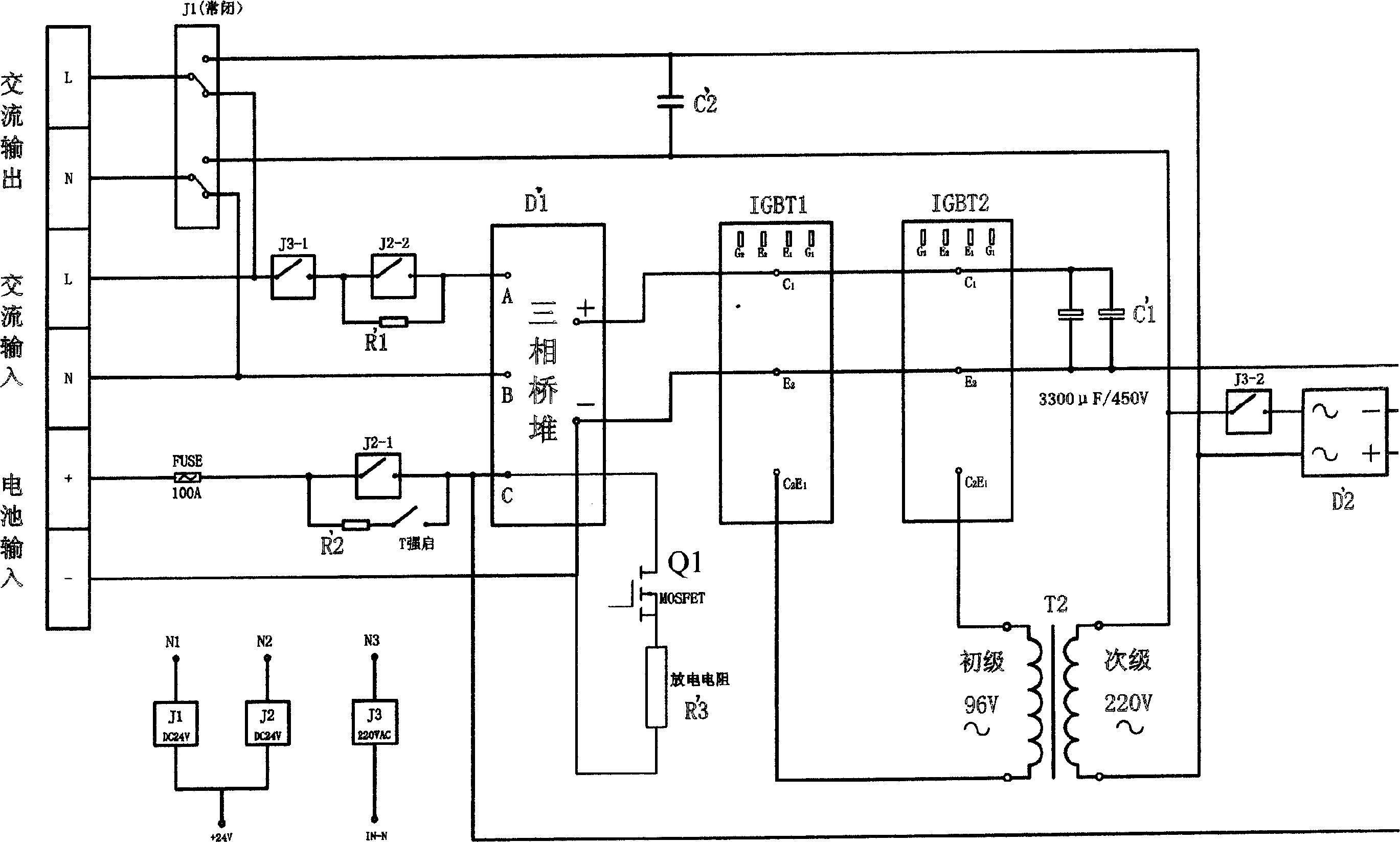
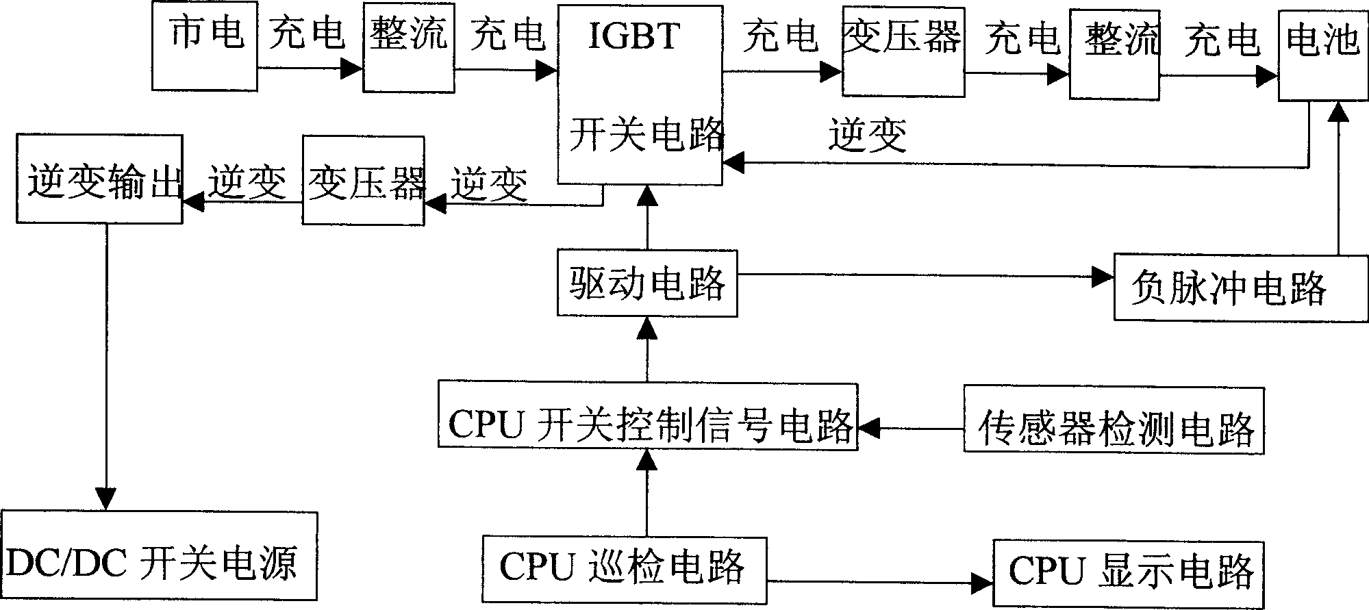
[0029] see Figure 1-Figure 3 , a negative pulse charging emergency power supply, which includes rectification, battery, IGBT switching circuit, DC / DC switching power supply, sensor detection circuit, inverter output, negative pulse circuit, CPU switch control signal circuit, CPU display circuit, CPU inspection Circuit, driving circuit, transformer T2, cooling system, relays J1, J2, J3, IGBT switching circuit is composed of composite device IGBT1 and composite device IGBT2, sensor detection circuit is composed of Hall current transformer, transformer T2 is reversible, inverter The primary when charging is the secondary when charging, and the secondary when inverting is the primary when charging.

[0030] The microcontroller IC4 is PIC16F74, the high-speed optocoupler U1 is TLP250, and the integrated block IC5 and integrated block IC6 are IR2110.

[00...


PUM


Abstract

A negative pulse charge emergency supply includes rectification, a battery, an IGBT switch\ circuit, a DC/DC switch supply, a transducer detection circuit, an inverse output, a negative pulse circuit, a CPU switch control signal circuit, a CPU display circuit, a CPU patrol inspection circuit, a drive circuit, a transformer, a cooling system and three relays. It has the negative pulse charging function and adds negative pulse to discharge properly based on the charging state to improve the charge receptance.

Description

1. Technical field [0001] The present invention relates to a power supply, more particularly to an emergency power supply (EPS). 2. Background technology [0002] In recent years, with the rapid development of my country's industrial and agricultural production and the improvement of people's living standards, the required power supply has also increased rapidly. Due to lack of electricity, blackouts often occur. Emergency power supply (EPS) must be used in order to ensure the power consumption of modern office buildings, large commercial places and service places, performance scenes, hospital operation lighting, etc. during power outages. At present, there are a few domestic manufacturers producing EPS. The existing EPS uses the following four charging methods: (1) Constant current charging method. like Figure 4 As shown, it is used to adjust the output voltage of the charging device or change the resistance in series with the battery to keep the ...

Claims


Application Information

Patent Timeline
IPC IPC(8): H02J7/10
Inventor 周熙文祁华琦
Owner 周熙文
Why Eureka
Try Eureka