Modified scheduling technique for a telecommunication system

A scheduler and transceiver technology, applied in the field of scheduling technology

Inactive Publication Date: 2005-10-26
QUALCOMM INC
View PDF0 Cites 1 Cited by
  • Summary
  • Abstract
  • Description
  • Claims
  • Application Information

AI Technical Summary

Problems solved by technology

Also, existing schedulers may unnecessarily schedule transmissions in neighboring cells or sectors simultaneously even though the system is not fully loaded, since the transceivers of neighboring cells are generally configured to start transmitting at the same point in time

Method used


Image

  • Modified scheduling technique for a telecommunication system
  • Modified scheduling technique for a telecommunication system
  • Modified scheduling technique for a telecommunication system

Examples


Embodiment Construction

[0027] The word "exemplary" is used herein to mean "serving as an example, instance, or illustration." Any embodiment described herein as "exemplary" is not necessarily to be construed as preferred or advantageous over other embodiments.

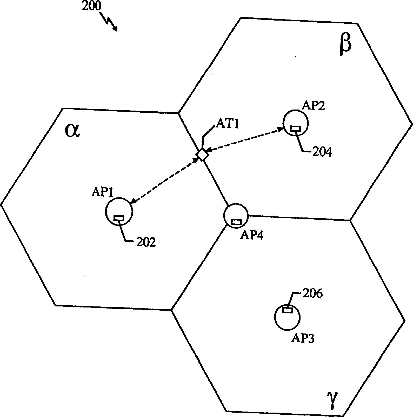
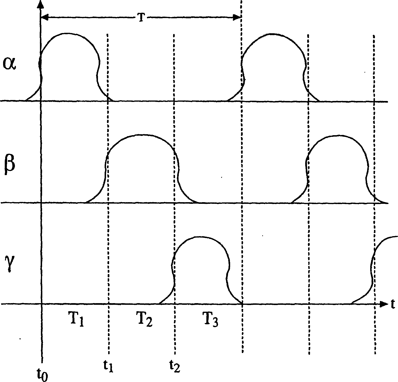
[0028] The term "cell" as used herein in the context of wireless communications refers to the coverage area of ​​a stationary base transceiver station configured to transmit signals to and receive signals from remote terminals. The term "sector" is generally used to refer to a subset of cells. Hereinafter, the term "cell" refers to both a cell and / or a sector within a cell.

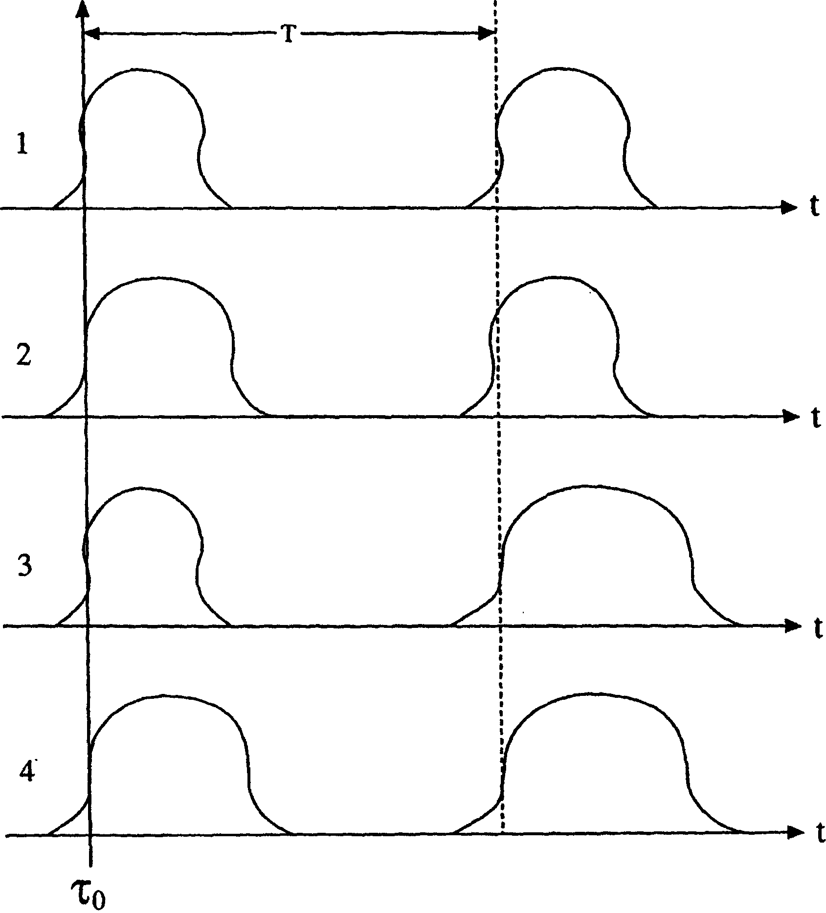
[0029] Recognizing the aforementioned difficulties associated with the conventional scheduling of transmission times for transceivers located in base stations in neighboring cells, this disclosure describes exemplary embodiments of improved scheduling that enables the transmission times of transceivers in neighboring cells to The transmission times are kept far enough...


PUM


Abstract

Biasing and scheduling transmission of data for access point transceivers. A transmission period of the transceivers is biased in adjacent cells into a plurality of time slots such that the biasing reduces interference among adjacent cells. The transceivers are then scheduled to transmit data packets during a selected time slot of the plurality of time slots that is distinct from each other.

Description

[0001] background technical field [0002] The present invention relates generally to telecommunications systems, and more particularly to scheduling techniques in such systems. Background technique [0003] Both Code Division Multiple Access 2000 (cdma2000) and Wideband Code Division Multiple Access (WCDMA) third generation (3G) data services are designed with respect to a physical layer framework that is optimized for voice transmission. Voice services are characterized by symmetrical traffic load (between forward and reverse links) and guaranteed quality of service (latency, delay, etc.). However, packet data services are characterized by an asymmetric traffic load that can include short messages (eg requests for data) and very long messages (eg data downloads). Consequently, systems that use voice traffic optimization for packet data services result in either a reduction in spectral efficiency or a reduction in the economics of these services...

Claims


Application Information

Patent Timeline
Patent Type & Authority Applications(China)
IPC IPC(8): H04Q1/00H04J13/00H04W16/00
CPCH04W16/00
Inventor P·J·布莱克
Owner QUALCOMM INC
Why Eureka
Try Eureka