

Bumper structure for vehicle
A bumper and vehicle technology, applied to vehicle components, vehicle safety arrangements, superstructure, etc., can solve the problems of no upper support, low rigidity, and detachment of fixed support frames, and achieve fewer parts points, ensure absorbency, and easy installation Effect
- Summary
- Abstract
- Description
- Claims
- Application Information
AI Technical Summary
Problems solved by technology
Method used
Image

Examples
Embodiment approach 1
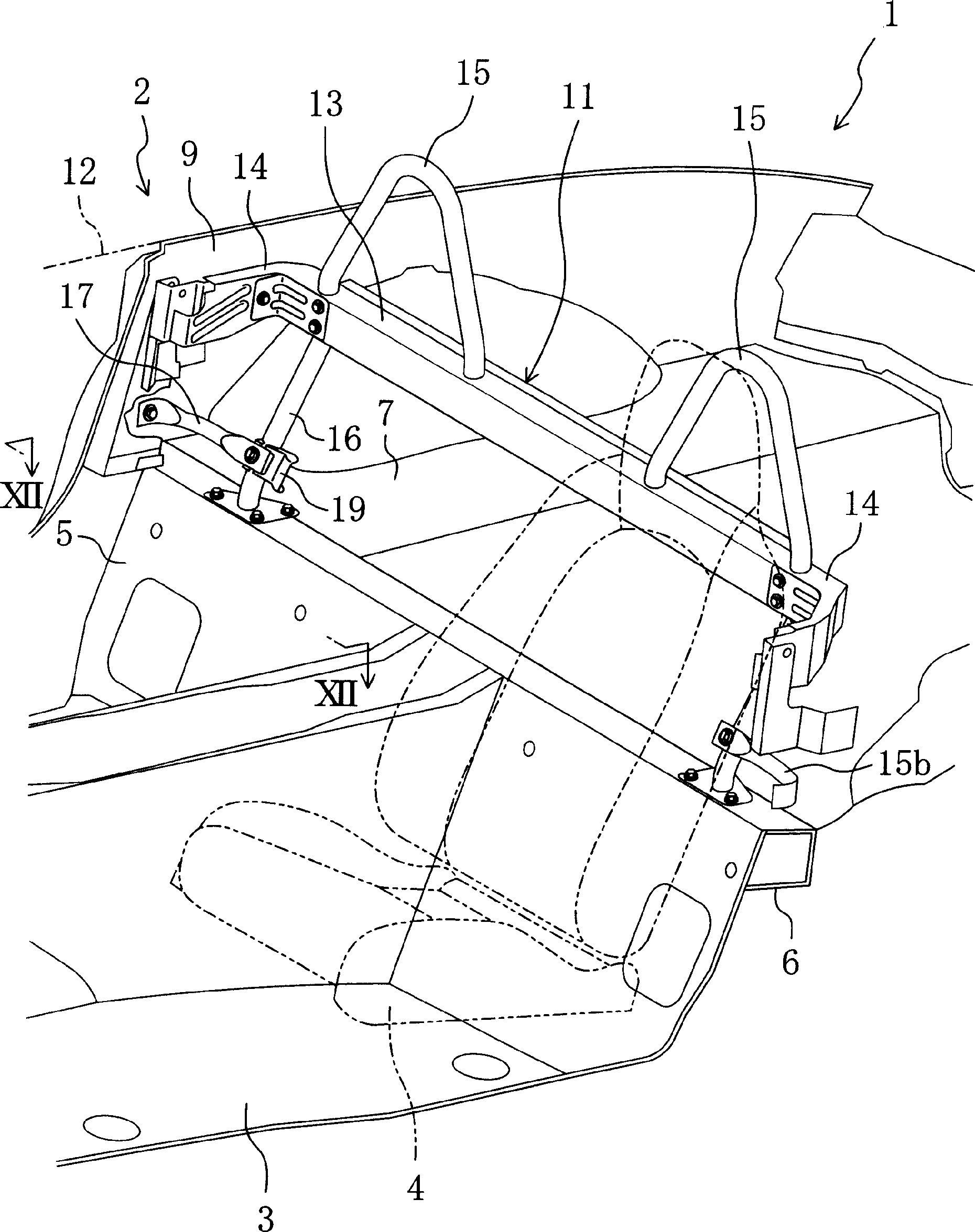
[0087] figure 1 , is seat 4 ( figure 1 Shown by the dotted line in 2) the perspective view of the rear side part. The vehicle body 1 includes: a front rib portion 3 , an upwardly bent portion 5 obliquely extending from the front rib portion 3 toward the rear of the vehicle body, a rear rib portion 7 , and left and right side panels 9 . Also, at the boundary between the upper end portion of the upwardly bent portion 5 and the rear rib portion 7, a horizontal frame 6 connecting the left and right side panels 9 is provided. And, in figure 1 In , the side panel 9 on the left side in the vehicle width direction is omitted.
[0088] Such as figure 2 As shown in an enlarged manner, the vehicle bumper structure 11 according to the present embodiment is provided on the left and right side panels 9 to connect the left and right side panels 9 . This vehicle bumper structure 11 is provided below the beltline 12 (beltline 12) of the convertible, and includes a crossbar (crossbar) mem...
Embodiment approach 2
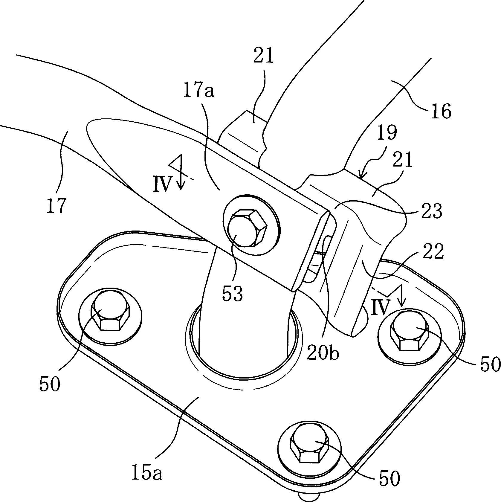
[0116] Figure 7 and Figure 8 The second embodiment of the present invention is shown, and differs from the first embodiment described above in that the structure of the fixed support frame 19 is different. And, with Figure 1 to Figure 4 The same symbols are used for the same parts and their detailed descriptions are omitted.
[0117] Such as Figure 7 As shown, two screw holes (not shown in the figure) are provided on the cross bar member 13 on the inner side in the vehicle width direction than the extended part 16 of the bumper member 15, and on these screw holes, bolts 50 are fixed. A loudspeaker mounting support frame 25 which is approximately in the shape of a rectangular plate as a support member. On the reverse side of this speaker mounting bracket 25, a speaker 26 as a vehicle-mounted device is mounted.
[0118] The vehicle width direction outer lower end portion of the above-mentioned loudspeaker mounting support frame 25 is also fixed by bolts 50 in the vehicl...
Embodiment approach 3
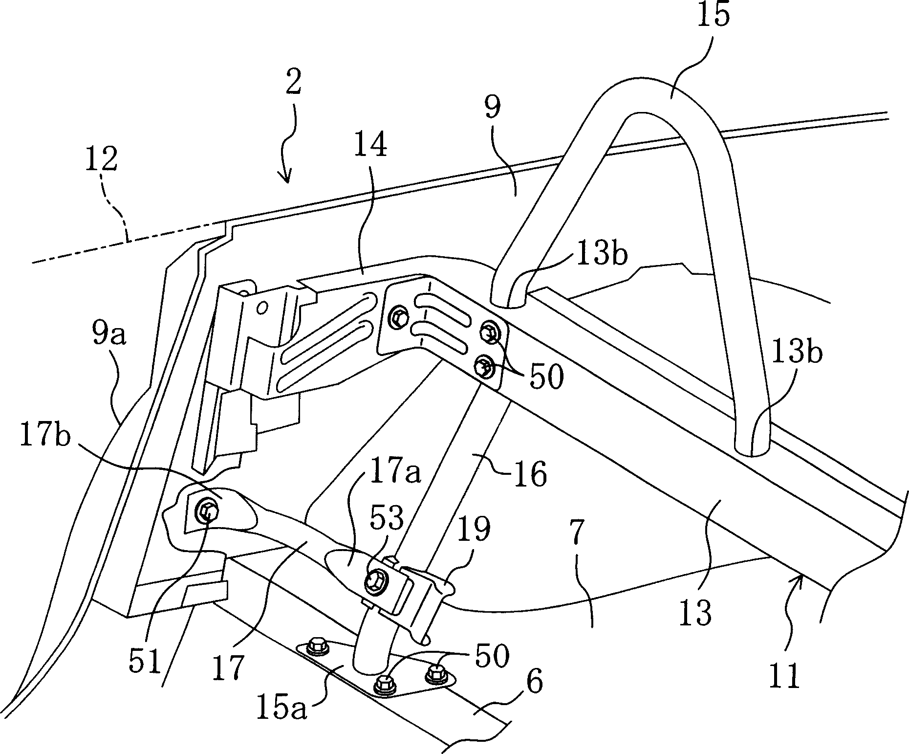
[0139] figure 2 , represents the side body structure 2 on the rear side of the right side vehicle seat (not shown) in the convertible. This side vehicle body structure 2 includes: a front rib portion 3 extending in the front-rear direction of the vehicle body, an upwardly bent portion 5 extending obliquely from the front rib portion 3 to the rear side of the vehicle body, and a rear rib portion 5 extending rearwardly. Rib portion 7, and left and right side panels 9. Also, if Figure 12 As shown, a horizontal frame 6 extending in the vehicle width direction is provided behind the upwardly bent portion 5 .
[0140] Such as Figure 13 As shown, the above-mentioned upward bending part 5 has its upper end bent backward, and the front side horizontal part of the "L" shaped part is welded on the back near its upper end, and the rear side extending upward from the horizontal part The upper end of the vertical part is welded to the front end side of the rear rib part 7 welded to the...
PUM
 Abstract
Description
Claims
Application Information