Liquid crystal display device

A technology of liquid crystal display device and liquid crystal display panel, which is applied in identification devices, nonlinear optics, optics, etc., can solve problems such as hindering the low-profile and miniaturization of electrical appliances, increasing the photoelectric effect, and the influence of reflected light from the bare chip, etc. The effect of preventing error display

Inactive Publication Date: 2003-12-24
PANASONIC CORP
View PDF0 Cites 0 Cited by
  • Summary
  • Abstract
  • Description
  • Claims
  • Application Information

AI Technical Summary

Problems solved by technology

[0004] However, in a liquid crystal display device as described above, in which the display is formed by reflection of light, the die not enclosed in the case is susceptible to being affected by the reflected light of the display.
Then, due to the presence of reflected light, the liquid crystal driver increases the photoelectric effect that causes false display
In addition, installing bare chips in the housing hinders the development of low-profile and miniaturized electrical appliances

Method used


Image

  • Liquid crystal display device
  • Liquid crystal display device
  • Liquid crystal display device

Examples


Embodiment Construction

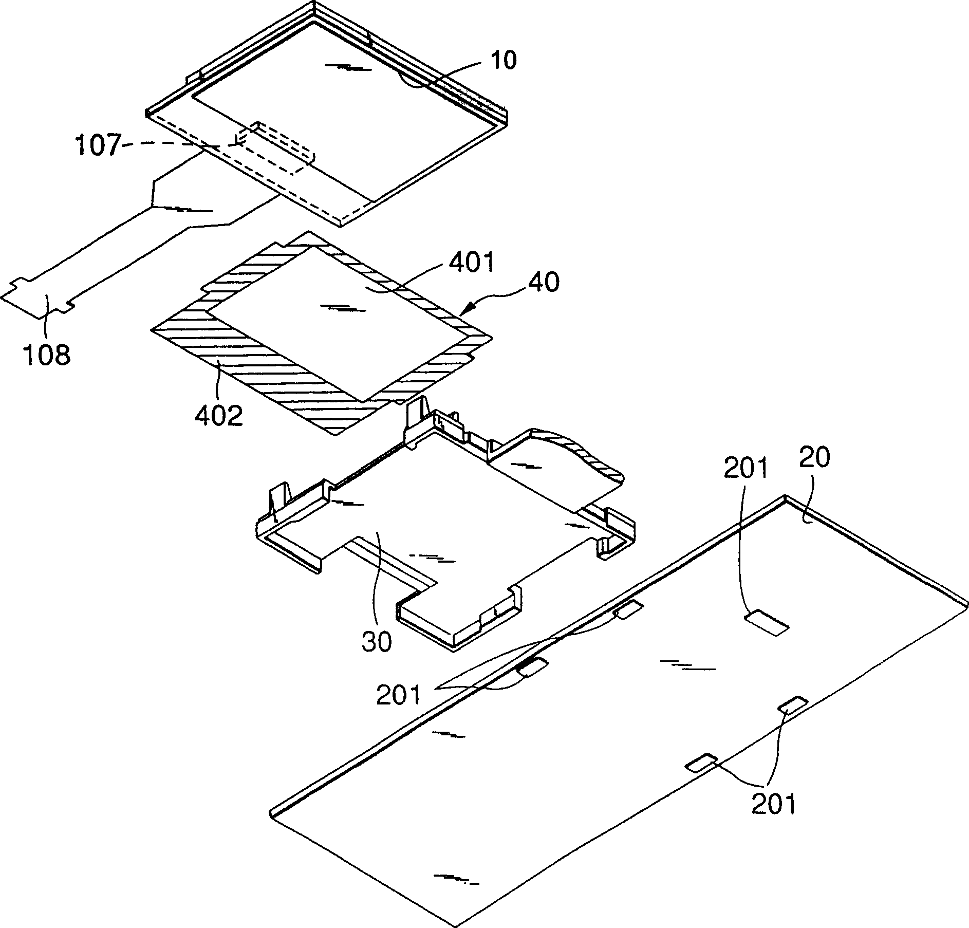
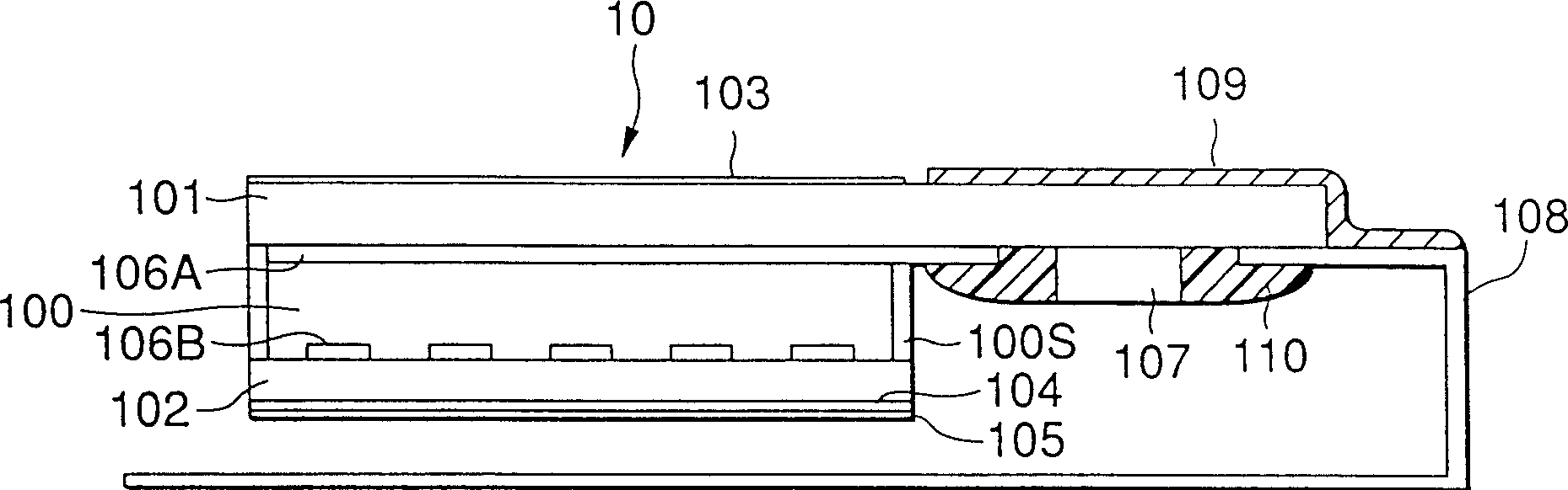
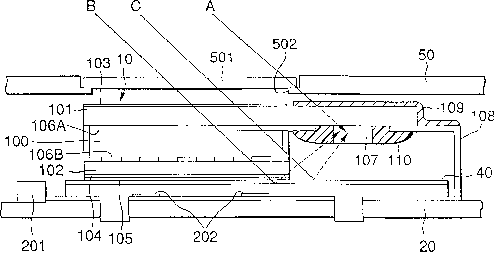
[0027] see now Figure 1 to Figure 3 A first embodiment of the present invention will be described. figure 1 is an exploded perspective view of the main part of the liquid crystal display device of the first embodiment of the present invention. figure 2 is a side view of the liquid crystal display panel portion of the liquid crystal display device of the embodiment of the present invention. image 3 It is a side view of the overall structure of the liquid crystal display device of the embodiment of the present invention.

[0028] from Figure 1 to Figure 3 It can be seen from the figure that the liquid crystal display device installed on the mobile phone terminal includes a liquid crystal display panel 10 , a circuit board 20 and a support plate 30 supporting the liquid crystal display panel 10 on the circuit board 20 .

[0029] from figure 2 It can be clearly seen from the figure that the liquid crystal display panel 10 includes: an upper plate 101 as a first plate, a l...


PUM


Abstract

Without housing a bare chip type liquid crystal driver within a package, to surely shield or absorb the light which reaches the liquid crystal driver so that erroneous display due to the photoelectric effect can be prevented. A light shielding tape 109 is affixed to the top surface of an upper panel 101 of a liquid crystal display panel 10 at an area which is opposite to the mounting area of a liquid crystal driver 107 mounted on the bottom surface of the upper panel 101. The light shielding tape 109 serves to shield the outer light incident on the liquid crystal driver 107. A diffusion sheet 40 composed of a light diffusing area 401 and a light absorbing area 402 located on the outer periphery thereof is arranged below the liquid display panel 10. The light diffusing area 401 serves to diffuse illumination light from a light source to the liquid crystal display panel 10, and the light absorbing area 402 serves to absorb the extraneous light incident on the liquid crystal driver.

Description

technical field [0001] The present invention relates to a liquid crystal display device which is assembled or mounted on various electrical appliances such as mobile phone terminals, and more particularly to a liquid crystal display device which can ensure a bare chip type liquid crystal driver against light. Background technique [0002] Generally, in a liquid crystal display device installed in various electric appliances, a bare chip constituting a liquid crystal driver is housed in a case, so that light irradiated on the bare chip can be shielded. [0003] With the development of low profile and miniaturization of various electrical appliances in recent years, the system for installing or assembling liquid crystal drivers has transitioned from surface mount to COB (chip on board), TCP (package on tape) and COG (chip on glass) mounted where the chip can be completely shielded from light by the molding material. In these systems, where the die-type liquid crystal driver i...

Claims


Application Information

Patent Timeline
Patent Type & Authority Patents(China)
IPC IPC(8): G09F9/00G02F1/13
CPCG02F1/136209G02F1/13454G02F2001/133317G02F1/133317
Inventor 五味美佳猪股阳二
Owner PANASONIC CORP
Why Eureka
Try Eureka