Constant flow pump and its manufacturing method

A technology of quantitative pump and flow direction, which can be used in injection devices, pumps, liquid distribution, etc., and can solve problems such as increased manufacturing costs

Inactive Publication Date: 2005-11-02
史蒂文・帕达尔
View PDF1 Cites 9 Cited by
  • Summary
  • Abstract
  • Description
  • Claims
  • Application Information

AI Technical Summary

Problems solved by technology

In addition, due to the complex structure of the pump, the production cost of such delivery devices becomes high

Method used


Image

  • Constant flow pump and its manufacturing method
  • Constant flow pump and its manufacturing method
  • Constant flow pump and its manufacturing method

Examples


Embodiment Construction

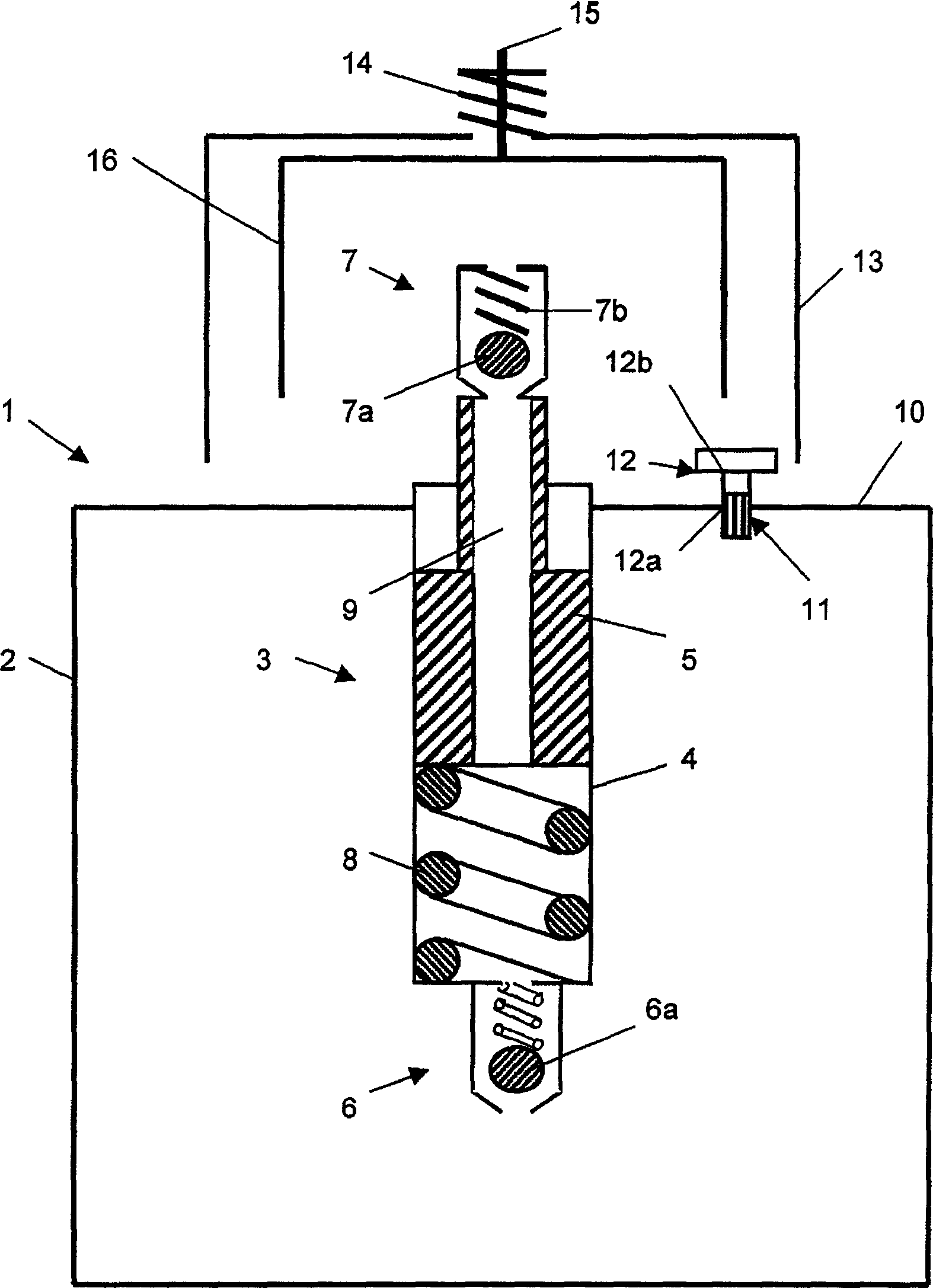
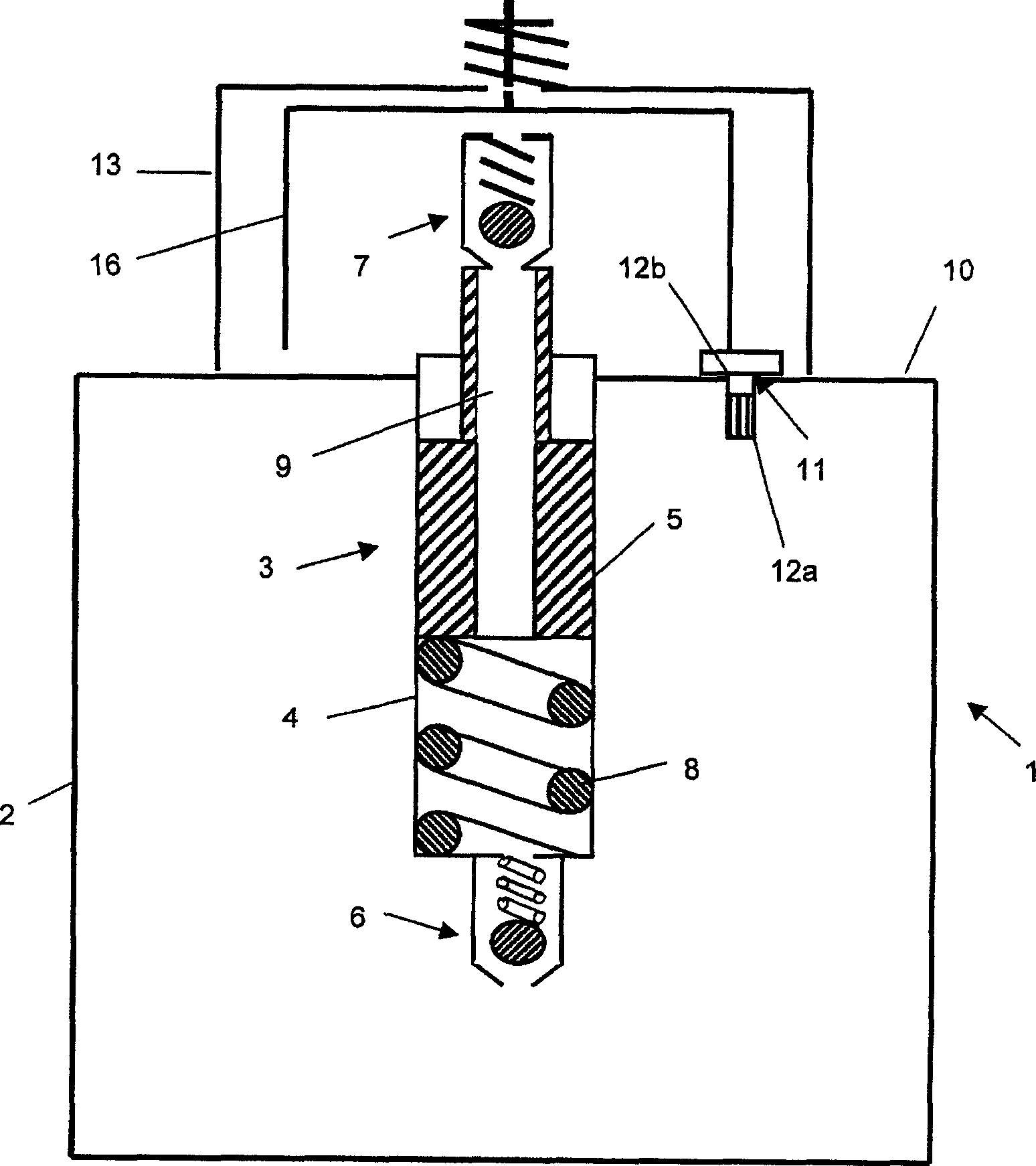
[0031] figure 1 and 2 The dosing pump device 1 shown in FIG. 1 has a container 2 that can be filled with a fluid, for example a liquid pharmaceutical or cosmetic product, and is formed by a collapsible bag. The container 2 is connected in a sealing manner to a pump 3 which, in the embodiment shown, comprises a pressure chamber 4 with a piston 5 sliding therein and two non-return valves 6 and 7 .

[0032] A spring 8 is arranged in the pressure chamber 4 to act upwardly on the piston 5 in the figure. The piston 5 has a central through-opening 9 through which fluid is drawn from the container 2 into the surroundings. For this purpose, the first non-return valve 6 is connected in such a way that when the spherical valve element 6 a is lifted from its valve seat due to the low pressure in the pressure chamber 4 , it allows a discharge from the container 2 to the flow in the pressure chamber 4. However, the flow in the opposite direction from the pressure chamber 4 into the cont...


PUM


Abstract

A metering pump arrangement has a container with a changeable volume for accommodating a fluid. The arrangement has a pump that can be connected with the container in a sealed manner, which can be manually activated. The pump has an outlet opening that is connected with the surroundings. A bypass channel runs outside the pump and connects the container with the surroundings. The bypass channel can be sealed off by way of a closure element. In the metering pump arrangement, remains air left in the container when filling can be pumped by simply struture. The invention also relates to application of the metering pump arrangement and manufacture method thereof.

Description

technical field [0001] The invention relates to a metered pump device having a container with a variable volume for receiving a fluid and a manually operable pump sealably connectable to said container, said pump having a Exit holes for ambient communication. Furthermore, the invention relates to the use of such a metering pump arrangement and to a method for producing said metering pump arrangement. Background technique [0002] A fluid dispensing device is known from DE 10049898 C2, with which, for example, liquid medicines or cosmetics can be dispensed quantitatively from a container. The metering pumps used for this work without air balance, wherein the liquid is accommodated in the container in an inner bag that is sealed from the surrounding environment and collapses when emptied. [0003] Usually such an inner bag is filled with a liquid such as medicine or cosmetics such that residual air remains in the inner bag. This is undesirable for various reasons. Oxygen i...

Claims


Application Information

Patent Timeline
Patent Type & Authority Applications(China)
IPC IPC(8): B05B11/00
CPCB05B11/0097B05B11/0043B05B11/026
Inventor 苏桑那·埃尔·哈京
Owner 史蒂文・帕达尔
Why Eureka
Try Eureka