Backlight module and light conducting plate therefor

A technology of backlight module and light guide plate, which is applied in optics, nonlinear optics, instruments, etc., can solve the problems of high manufacturing cost and complex manufacturing process of backlight module, so as to reduce manufacturing difficulty and manufacturing cost, and improve light guiding ability. , to avoid the effect of shape distortion

Inactive Publication Date: 2005-11-02
HONG FU JIN PRECISION IND (SHENZHEN) CO LTD +1
View PDF1 Cites 2 Cited by
  • Summary
  • Abstract
  • Description
  • Claims
  • Application Information

AI Technical Summary

Problems solved by technology

[0006] In order to overcome the problems of complex manufacturing process and high manufacturing cost of the pr

Method used


Image

  • Backlight module and light conducting plate therefor
  • Backlight module and light conducting plate therefor
  • Backlight module and light conducting plate therefor

Examples


Embodiment Construction

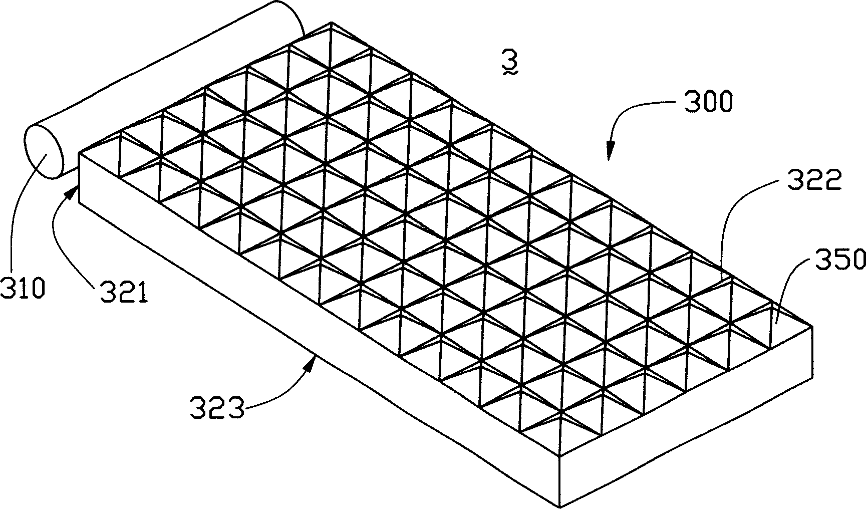
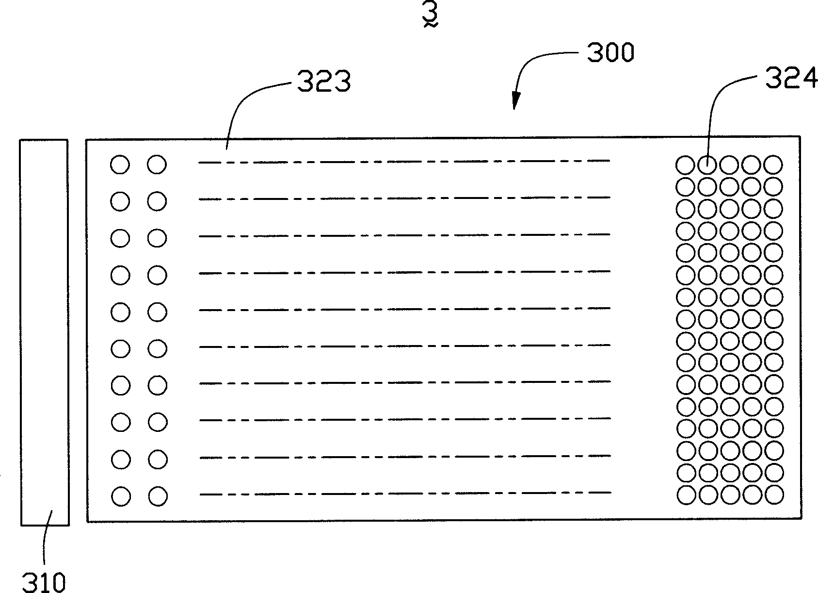
[0015] see image 3 and FIG. 4 are respectively an exploded perspective view of the backlight module of the present invention and a bottom view of the bottom surface of the backlight module. The backlight module 1 of the present invention includes a light guide plate 11 and a light source 12 , and the light guide plate 11 includes a light incident surface 111 , a bottom surface 112 and a light output surface 113 . The light incident surface 111 is used to receive the light beam emitted by the light source 12, and the bottom surface 112 is connected to the light incident surface 111. In order to improve the utilization rate of the light beam, the bottom surface 112 is coated with a reflective film (not shown), and the light exit surface 113 and the bottom surface 112 is opposite and guides the light beam in the light guide plate 11; the light source 12 is arranged opposite to the light incident surface 111 to provide light beams for the light guide plate 11; the bottom surface ...


PUM


Abstract

The invention discloses a backlight mold set, which comprises a light-guide plate and a light source. The light-guide plate comprises an incidence surface opposite to light source, a floor and a reflection surface. Set multiple micro-grids divided evenly underside of light-guide plate, and set grid dots in some micro-grids.

Description

【Technical field】 [0001] The invention relates to a backlight module for a liquid crystal display and a light guide plate thereof. 【Background technique】 [0002] Liquid crystal display is a non-self-luminous display device, and its display is mainly realized by controlling the passage or non-passage of the light beam emitted by the external light source. Therefore, an external light source and a corresponding light guide device are required. The emitted light beam is directed towards the display panel. [0003] A kind of backlight module of prior art can refer to No. 558,014 of Chinese Taiwan patent announced on October 11, 2003, as figure 1 As shown, the backlight module 3 includes a light guide plate 300 and a light source 310 located on one side of the light guide plate 300 . The light source 310 is usually covered by a light source cover (not shown) on the back of the light source 310 relative to the light guide plate 300 to increase the ratio of light beams emitted b...

Claims


Application Information

Patent Timeline
IPC IPC(8): G02F1/1335
Inventor 林志泉
Owner HONG FU JIN PRECISION IND (SHENZHEN) CO LTD
Why Eureka
Try Eureka