Fluorescent bulb retaining spring

一种支承弹簧、荧光灯的技术,应用在荧光灯领域,达到可靠减负的效果

Inactive Publication Date: 2005-11-09
VOSSLOH SCHWABE DEUT GMBH
View PDF0 Cites 0 Cited by
  • Summary
  • Abstract
  • Description
  • Claims
  • Application Information

AI Technical Summary

Problems solved by technology

However, UV-resistant plastics must be used for this, since fluorescent lamps always emit a considerable amount of UV light, which leads to a corresponding load on the plastic, at least in the vicinity of the lamp

Method used


Image

  • Fluorescent bulb retaining spring
  • Fluorescent bulb retaining spring

Examples


Embodiment Construction

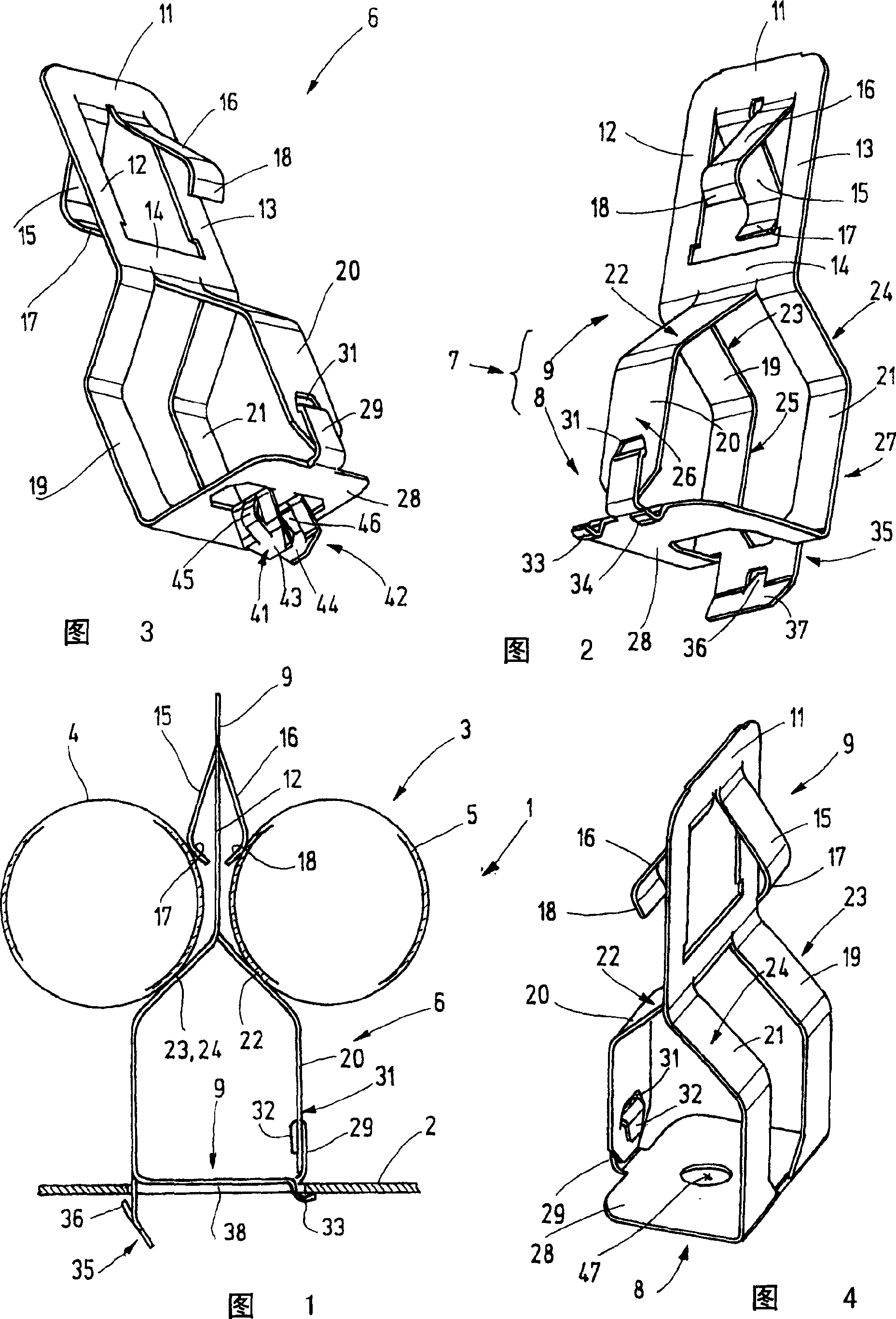
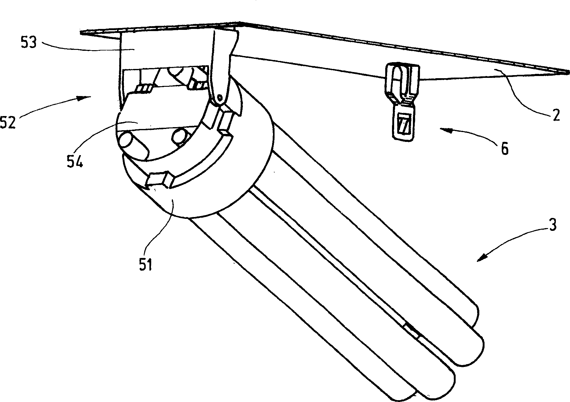
[0020] 1 shows a section through a luminaire 1 with a luminaire housing 2 and a fluorescent lamp 3 having a U-shaped discharge vessel whose branches 4 , 5 are arranged parallel to one another at a small distance. The discharge tube has a plug at one end. The plug and its socket are shown in FIG. 1 . In the case of a relatively large distance from the lamp cap, a support spring 6, which supports the free-floating end of the fluorescent lamp 3, is preferably provided approximately at the end of the discharge vessel, ie in the vicinity of the interconnected end of the branch tubes 4, 5. On the lamp housing 2. This not only applies to the horizontal installation of the fluorescent lamp 3 as shown in Figure 1, but also to the imaginary suspension installation when Figure 1 is turned upside down, or the horizontal installation with side lamp housing when Figure 1 is rotated 90°. . The support spring 6 can also be used for the vertically arranged fluorescent lamps 3 to fix the flu...


PUM


Abstract

A fluorescent bulb retaining spring ( 6 ) comprises a one piece, sheet-metal stamped and bent part, entirely and seamlessly comprised of one material. The retaining spring ( 6 ) can be produced especially simply from one rectangular piece of sheet metal of substantially uniform thickness, with all functional parts and functional regions created by cutting out spring tongues and bending them outwardly from the sheet. Connecting legs between a bulb retainer portion ( 9 ) and a fastening portion ( 8 ) form an annular region which is closed in force-locking fashion by a crimped connection ( 29, 31, 32 ), which can be produced in automated fashion as part of the stamping and bending operation.

Description

technical field [0001] The invention relates to a support spring for a fluorescent lamp, especially a fluorescent lamp having a plug at one end. Background technique [0002] Fluorescent lamps with a plug at one end, so-called compact fluorescent lamps, tend to be of considerable length. Since this lamp only has a plug at one end, it is not at all problematic to be installed in a horizontal installation position, that is, it needs an additional supporting device to support, for example, the end of the u-shaped curved discharge tube corresponding to the plug, so as to avoid the plug and the lamp. The seat is subjected to bending stress. Such bending stresses can lead to serious damage and related damages. [0003] It is known, in practice, that fluorescent lamps with a plug at one end are supported at their ends by a plastic support which, in certain constructions, is also provided with a metal spring. However, UV-resistant plastics must be used for this, since fluorescent...

Claims


Application Information

Patent Timeline
Patent Type & Authority Applications(China)
IPC IPC(8): F21V19/00
CPCF21Y2103/00F21V19/009
Inventor B·凯恩H·-P·穆斯
Owner VOSSLOH SCHWABE DEUT GMBH
Why Eureka
Try Eureka