
Generator-motor

A technology for generator motors and electrode plates, which is applied in the direction of synchronous generators, etc., can solve problems such as the difficulty in shortening the length of wiring, the difficulty in obtaining the size of the starter generator, and the difficulty in improving the efficiency of cooling power components, etc., to achieve short wiring and reduce the area Effect

Inactive Publication Date: 2005-11-09
TOYOTA JIDOSHA KK
View PDF1 Cites 5 Cited by
  • Summary
  • Abstract
  • Description
  • Claims
  • Application Information

AI Technical Summary

Problems solved by technology

Therefore, it is difficult to obtain a starter generator with a smaller size
[0007] Especially, the same problem occurs when a control circuit is incorporated in the generator to control the generator installed in the engine
[0008] Since Japanese Patent Laid-Open No. 2-266855 does not clearly disclose the position of the electrodes contained in the power pack, it is difficult to improve the efficiency of cooling the power pack in the conventional starter generator
[0009] In addition, since Japanese Patent Laid-Open No. 2-266855 also does not clearly disclose the position of the wiring connected to the power supply unit, it is difficult to shorten the length of the wiring and simplify the wiring in the conventional starter generator

Method used


Image

  • Generator-motor
  • Generator-motor
  • Generator-motor

Examples


Embodiment Construction

[0047] Hereinafter, embodiments of the present invention will be described in detail with reference to the accompanying drawings. It should be noted that the same reference numerals designate the same or corresponding elements in the drawings.

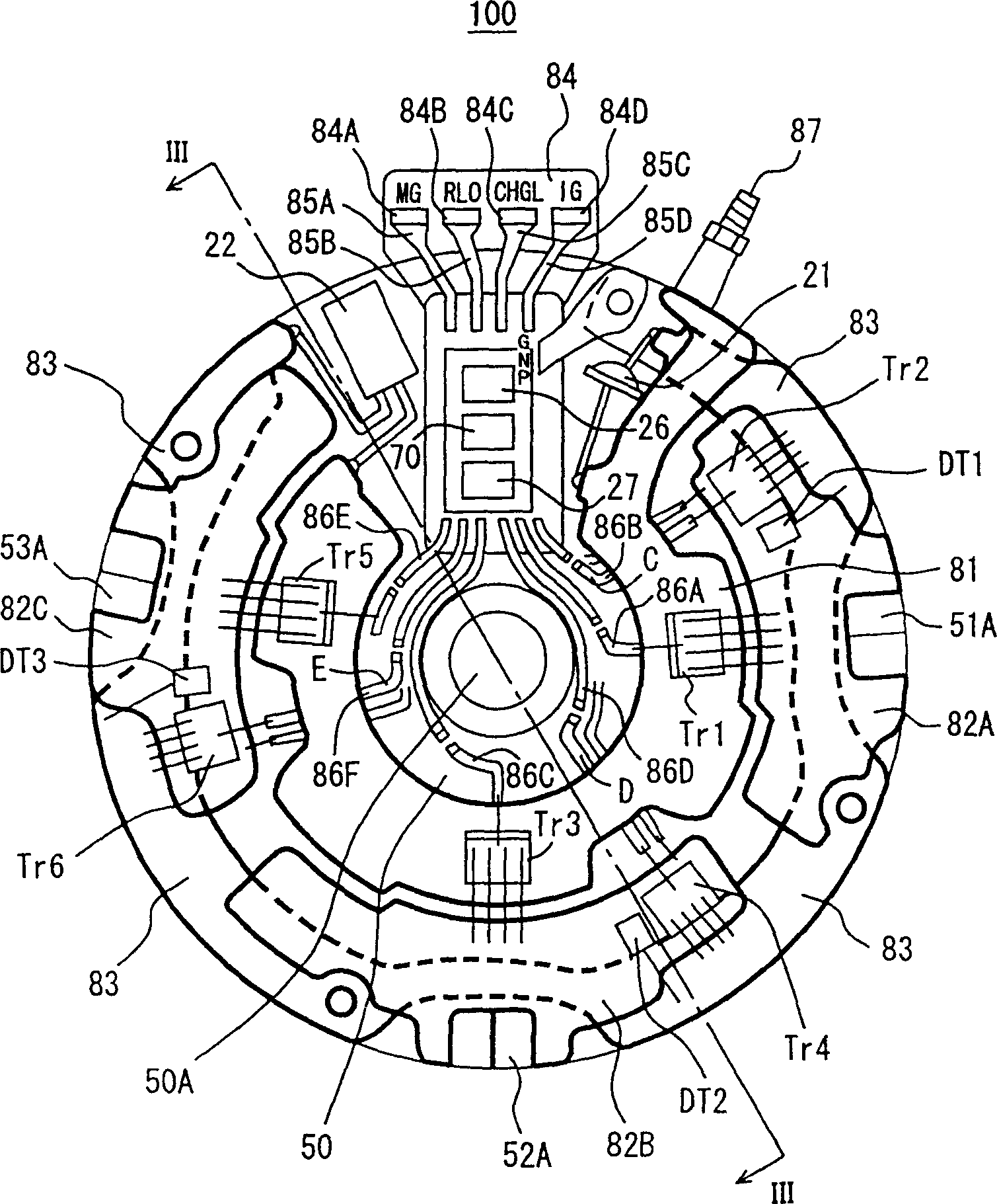
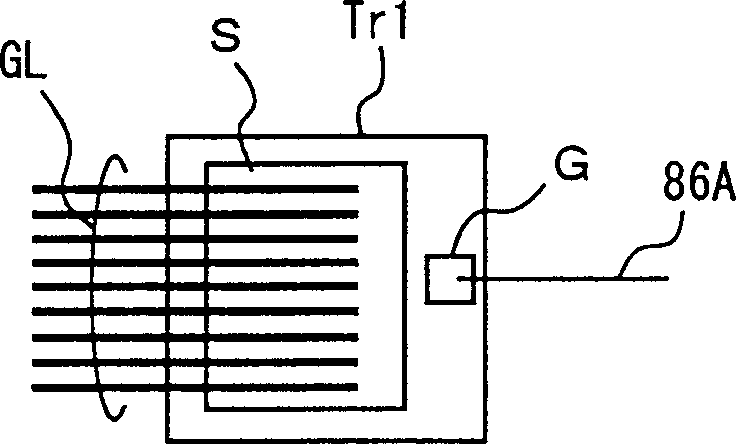
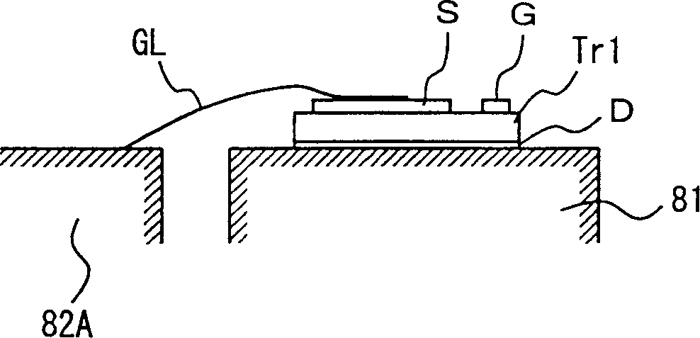
[0048] refer to figure 1 , the generator motor 100 according to the present invention includes Zener diodes 21, DT1 to DT3, MOS transistors Tr1 to Tr6, power supply 26, MOS driver 27, alternator 50, custom integrated circuit (IC) 70, electrode plates 81, 82A to 82C, 83, a substrate 84, terminals 84A to 84D, and wiring 85A to 85D, 86A to 86D.

[0049] Electrode plates 81 , 82A to 82C, 83 and a base plate 84 are formed on one end face of the alternator 50 . The electrode plate 81 is substantially U-shaped and surrounds the rotation axis 50A of the alternator 50 . The electrode plates 82A to 82C are arranged to substantially form a U shape outside the electrode plate 81 to surround the electrode plate 81 . The electrode plates 82A to...


PUM


Abstract

A power-generating dynamo-electric apparatus 100 is equipped with an alternator 50, electrode plates 81, 82A-82C, 83, a board 84, MOS transistors Tr1-Tr6, and a MOS driver 27. The electrode plates 81, 82A-82C, and 83 are arranged in roughly U shape such that they surround the rotating shaft 50A of the alternator 50 at the end face of the alternator 50. The MOS transistors Tr1, Tr3, and Tr5 are arranged on the electrode plate 81, and the MOS transistors Tr2, Tr4, and Tr6 are arranged on the electrode plates 82A, 82B, and 82C, respectively. The MOS driver 27 is arranged on the board 84 arranged in a roughly U-shaped cut so as to control the ON / OFF of the MOS transistors Tr1-Tr6.

Description

technical field [0001] The present invention relates to a generator motor including control means on the end face, and more particularly to a compact generator motor. Background technique [0002] Japanese Patent Laid-Open No. 2-266855 discloses a starter generator that can be used as a three-phase motor for starting an on-vehicle engine and also as a three-phase alternator for charging a battery. [0003] refer to Figure 9 , The starter generator 300 disclosed in Japanese Patent Laid-Open No. 2-266855 includes a motor (motor) unit 301 and a drive unit 302 . The motor unit 301 includes a stator and a rotor. The drive unit 302 is provided on the end surface 301A of the motor unit 301 . The driving unit 302 includes a cylindrical part 302A and a power supply assembly 302B. The power supply assembly 302B is formed on one surface of the cylindrical member 302A. That is, the power source assembly 302B is disposed in a direction perpendicular to the radial direction 303 of th...

Claims


Application Information

Patent Timeline
Patent Type & Authority Applications(China)
IPC IPC(8): H02K19/36
Inventor 久须美秀年
Owner TOYOTA JIDOSHA KK
Learn More