
Air spinning machine

An open-end spinning machine, air-flow technology, applied in the direction of spinning machine, continuous winding spinning machine, textile and paper making, etc.

Pending Publication Date: 2021-12-10
MURATA MASCH LTD
View PDF1 Cites 0 Cited by
  • Summary
  • Abstract
  • Description
  • Claims
  • Application Information

AI Technical Summary

Problems solved by technology

[0007] In this way, in the layout of Japanese Utility Model Publication No. 05-064172, there is substantially no opportunity for the suction airflow of the slack tube to act on the yarn on the package side to suck it in, and it is difficult to reliably catch the yarn to the slack tube.

Method used


Image

  • Air spinning machine
  • Air spinning machine
  • Air spinning machine

Examples


Embodiment Construction

[0034] An air spinning machine 1 according to one embodiment of the present invention will be described with reference to the drawings.

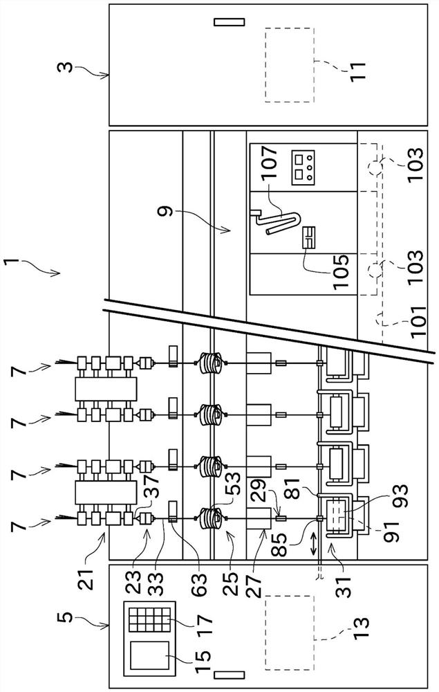
[0035] Such as figure 1 As shown, the air spinning machine 1 includes a blower box 3 , a power box 5 , a plurality of spinning units 7 , and a piecing cart 9 . The plurality of spinning units 7 are arranged side by side in a predetermined direction.

[0036] A blower 11 and the like functioning as a negative pressure source are arranged in the blower box 3 .

[0037] A drive source (not shown), a central controller 13 , a display unit 15 , and an operation unit 17 are arranged in the power box 5 . The driving source provided in the power box 5 includes an electric motor commonly used by the plurality of spinning units 7 .

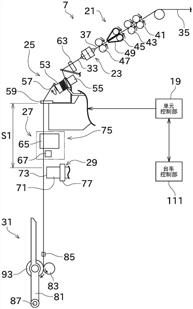
[0038] The central control device 13 centrally manages and controls each part of the air spinning machine 1 . The central control device 13 communicates with each spinning unit 7 such as figure 2 The unit control un...


PUM


Abstract

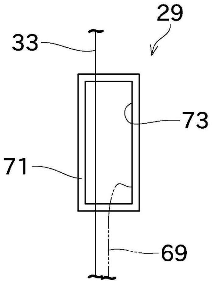
The invention provides an air spinning machine, comprising a drafting device (21), an air spinning device (23), a yarn accumulating device (25), a yarn intervening device (27), a suction device (29) and a winding and taking device (31). The air spinning device (23) twists the sliver (35) that is drafted by a drafting device (21), that is, a fiber bundle (37) by twisting air flow to generate a spun yarn (33). The air spinning device (23) twists sliver (35) that is drafted by the drafting device (21), that is, the fiber bundle (37) by the twisting air flow to generate the spun yarn (33). The yarn accumulating device (25) temporarily accumulates the spun yarn. The yarn intervention device (27) intervenes in the spinning. The suction device (29) is configured to suction and spin the yarn. The winding and taking device (31) winds up the spun yarn to form a package (93). The drafting device, the air spinning device, a yarn accumulating device, the yarn intervening device, the suction device, and the winding device are arranged in this order from a high position to a low position. The yarn intervention device (27) is a waxing device (65) and a yarn travel sensor (67).

Description

technical field [0001] The invention relates to an air spinning machine. Background technique [0002] Conventionally, there is known an air spinning machine provided with a piecing device that performs piecing when a yarn is broken. Patent Document 1 discloses such a spinning machine. [0003] The spinning machine disclosed in Japanese Patent Application Laid-Open No. 05-064172 includes a spinning nozzle, a piecing device, and a winding device. The piecing device is arranged downstream of the spinning nozzle in the yarn traveling direction. The piecing device includes a package-side yarn end catching device, a spinning unit side yarn end catching device, and a piecing component. The suction nozzle of the package side yarn end catching device has a yarn end suction port. The yarn end suction port can suck the yarn on the package (winding device) side. [0004] The spinning machine disclosed in Japanese Patent Application Laid-Open No. 05-064172 is provided with a slack ...

Claims


Application Information

Patent Timeline
Patent Type & Authority Applications(China)
IPC IPC(8): D01H1/115D01H1/14D01H15/00D01H13/04D01H13/30
CPCD01H1/115D01H1/14D01H15/00D01H13/04D01H13/308
Inventor 重山昌澄
Owner MURATA MASCH LTD
Learn More