Swing direct drive device and method built in solenoid coil
A solenoid coil, direct drive technology, applied to the power device inside the switch, valve operation/release device, valve device and other directions, can solve the problems of easy failure, many parts, inconvenience, etc., and achieve a wide range of applications , compact structure
- Summary
- Abstract
- Description
- Claims
- Application Information
AI Technical Summary
Problems solved by technology
Method used
Image
Examples
no. 1 example
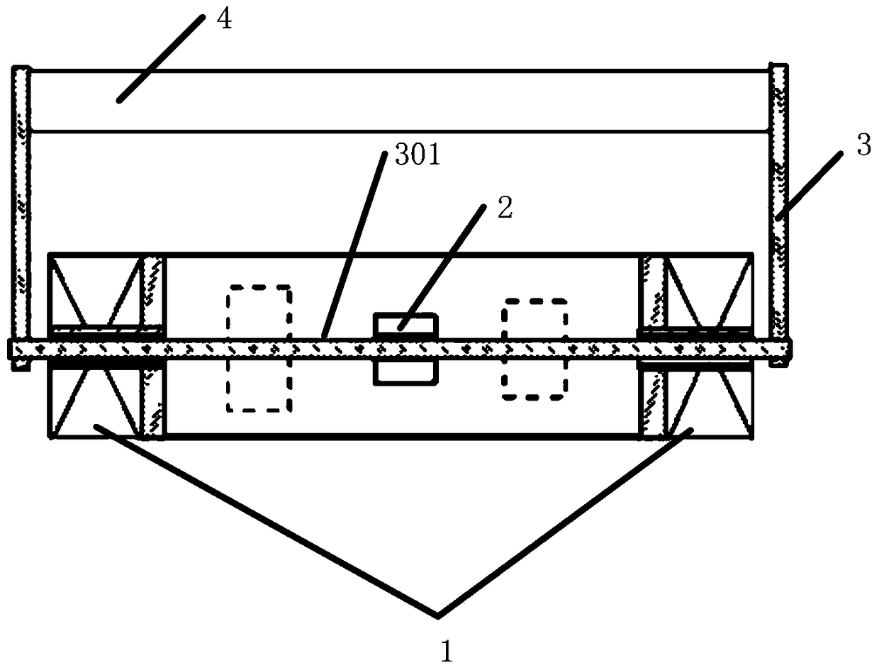
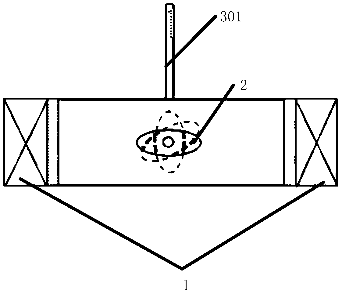
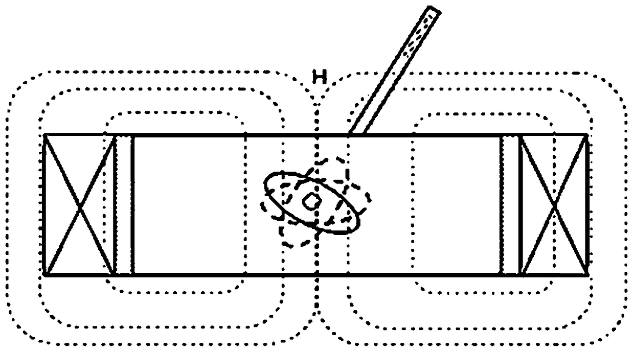
[0053] figure 1 , figure 2 , image 3 It is a structural schematic diagram of the swing direct drive device built in the solenoid coil in the first embodiment of the present invention. The first embodiment is a preferred example of the above-mentioned basic embodiment. In this embodiment, the swing direct drive device built in the solenoid coil includes a solenoid coil 1, a magnet 2, and a transmission assembly 3; the magnet 2 can be It is an electromagnet or a permanent magnet; the magnet 2 is located inside the solenoid coil 1; the magnet 2 is connected to the transmission assembly 3, and the transmission assembly 3 extends from the inside of the solenoid coil 1 to the outside of the solenoid coil 1; the solenoid coil 1 Applying a magnetic force to the magnet 2 causes the magnet 2 to rotate; the magnet 2 rotates and drives the transmission assembly 3; the number of the magnet 2 is one or more.
[0054] Among them, the solenoid coil 1 interacts with the magnet 2 to form a...
no. 2 example
[0057] Figure 4 , Figure 5 It is a structural schematic diagram of the swing direct drive device built in the solenoid coil in the second embodiment of the present invention. The second embodiment is a preferred example of the above-mentioned basic embodiment. In this embodiment, the swing direct drive device built in the solenoid coil includes a solenoid coil 1, a magnet 2, and a transmission assembly 3; the magnet 2 can be It is an electromagnet or a permanent magnet; the magnet 2 is located inside the solenoid coil 1; the magnet 2 is connected to the transmission assembly 3, and the transmission assembly 3 extends from the inside of the solenoid coil 1 to the outside of the solenoid coil 1; the solenoid coil 1 Applying a magnetic force to the magnet 2 causes the magnet 2 to rotate; the magnet 2 rotates and drives the transmission assembly 3; the number of the magnet 2 is one or more.
[0058] Among them, the solenoid coil 1 interacts with the magnet 2 to form a magnetic...
no. 3 example
[0061] Figure 6 , Figure 7 It is a structural schematic diagram of the swing direct drive device built in the solenoid coil in the third embodiment of the present invention. The third embodiment is a preferred example of the above-mentioned basic embodiment. In this embodiment, the swing direct drive device built in the solenoid coil includes a solenoid coil 1, a magnet 2, and a transmission assembly 3; the magnet 2 can be It is an electromagnet or a permanent magnet; the magnet 2 is located inside the solenoid coil 1; the magnet 2 is connected to the transmission assembly 3, and the transmission assembly 3 extends from the inside of the solenoid coil 1 to the outside of the solenoid coil 1; the solenoid coil 1 Applying a magnetic force to the magnet 2 causes the magnet 2 to rotate; the magnet 2 rotates and drives the transmission assembly 3; the number of the magnet 2 is one or more.
[0062] Among them, the solenoid coil 1 interacts with the magnet 2 to form a magnetic c...
PUM
 Abstract
Description
Claims
Application Information
 - R&D
- Intellectual Property
- Life Sciences
- Materials
- Tech Scout
- Unparalleled Data Quality
- Higher Quality Content
- 60% Fewer Hallucinations
Browse by: Latest US Patents, China's latest patents, Technical Efficacy Thesaurus, Application Domain, Technology Topic, Popular Technical Reports.
© 2025 PatSnap. All rights reserved.Legal|Privacy policy|Modern Slavery Act Transparency Statement|Sitemap|About US| Contact US: help@patsnap.com


