
Quick clamping head for electric jig saw

A curve saw, fast technology, applied in the direction of sawing machine, metal sawing equipment, metal processing equipment, etc., can solve the problems of complicated processing and manufacturing, easy movement of knife and saw blades, low work efficiency, etc., and achieve simple structure, not easy to move dynamic and high work efficiency

Inactive Publication Date: 2005-11-16
张勤业
View PDF0 Cites 10 Cited by
  • Summary
  • Abstract
  • Description
  • Claims
  • Application Information

AI Technical Summary

Problems solved by technology

Its structure is complicated, the processing and manufacturing are complicated, the cost is high, the saw blade is easy to move during use, and the saw blade cannot be retracted automatically, and the work efficiency is low.

Method used


Image

  • Quick clamping head for electric jig saw
  • Quick clamping head for electric jig saw
  • Quick clamping head for electric jig saw

Examples


Embodiment Construction

[0012] Describe in detail below in conjunction with accompanying drawing and embodiment:

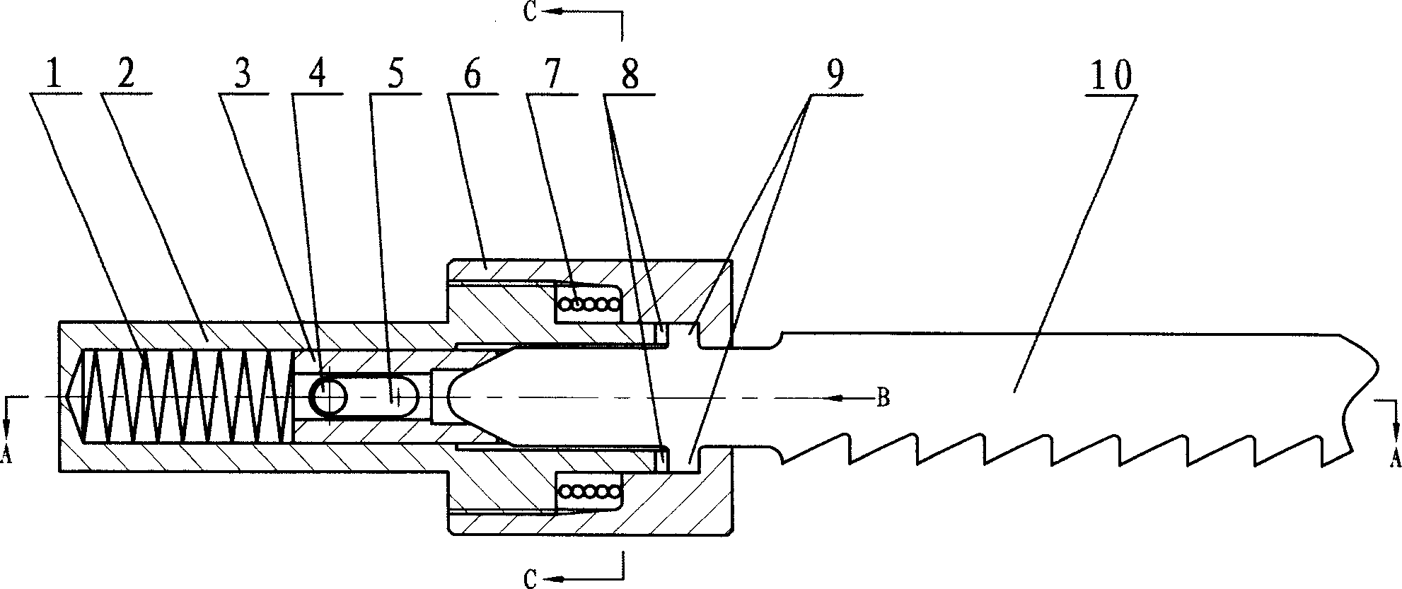
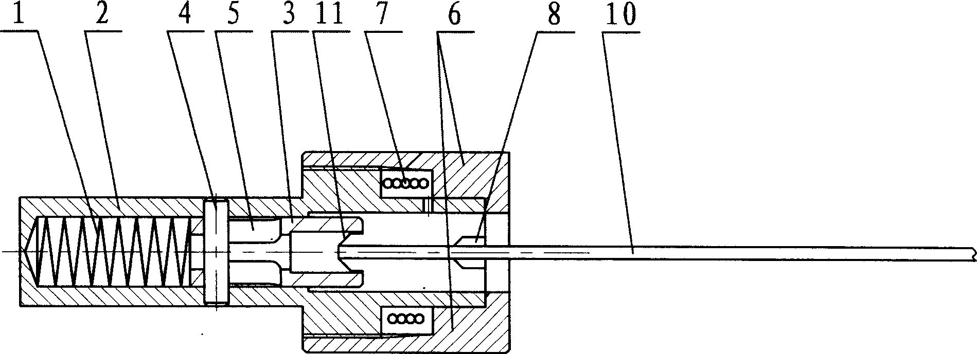
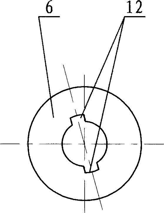
[0013] figure 1 The utility model relates to a quick chuck of an electric curve saw of the present invention. Including clip 2, lock sleeve 6, lock sleeve reset torsion spring 7, the main points are: the lock sleeve 6 and clip 2 are provided with matching right-handed reset tightening threads, and the inner cavity of clip 2 is provided with a pressure Spring 1 is provided with the positioning pressing piece 3 that slides and is positioned in the clip part 2 inner cavity before the stage clip 1, and the positioning pressing piece 3 front end is provided with knife saw end positioning groove 11. When installing the knife saw blade 10, as long as the lock sleeve 6 is left-handed until the slot 12 provided on the lock sleeve 6 is parallel to the saw end positioning groove 11 provided on the front end of the positioning pressure piece 3, the knife saw blade 10 is inserted. Push the knife an...


PUM


Abstract

A fast fixture for the electric curve saw is composed of clamping unit, locking sleeve, restoring torsional spring for locking sleeve, and the locating-pressing part with front locating slot for saw blade and the tensional spring, which are installed in the cavity of said clamping unit.

Description

technical field [0001] The invention relates to a chuck of an electric tool, in particular to a quick chuck of an electric curve saw. Background technique [0002] The existing quick chucks of electric jigsaws all use the groove provided on the cam sleeve to press the cam, the cam to press the saw blade, and the shoulder provided on the saw blade and the lock sleeve provided with The slots are misaligned to lock the blade of the knife. Its structure is complicated, the processing and manufacturing are complicated, and the cost is high. The saw blade is easy to move when in use, and the saw blade cannot be retracted automatically, so the work efficiency is low. Contents of the invention [0003] In view of the above problems, the object of the present invention is to provide a quick chuck of electric jigsaw with simple structure and easy manufacturing. [0004] A fast chuck for an electric jigsaw, including a clip, a lock sleeve...

Claims


Application Information

Patent Timeline
IPC IPC(8): B23D51/08
Inventor 张勤业
Owner 张勤业
Learn More