Valve throttle dynamic control method for eliminating serious slug flow

A technology of dynamic control and control method, applied in pipeline systems, mechanical equipment, gas/liquid distribution and storage, etc., can solve problems such as excessive throttling, prevent excessive throttling, suppress severe slug flow, and solve excessive throttling. flow effect

Inactive Publication Date: 2005-11-23
XI AN JIAOTONG UNIV
View PDF0 Cites 12 Cited by
  • Summary
  • Abstract
  • Description
  • Claims
  • Application Information

AI Technical Summary

Problems solved by technology

[0004] The purpose of the present invention is to provide a valve throttling dynamic control method for eliminating severe slug flow, which can not only suppress severe slug flow, but also automatically adjust the opening o

Method used


Image

  • Valve throttle dynamic control method for eliminating serious slug flow
  • Valve throttle dynamic control method for eliminating serious slug flow
  • Valve throttle dynamic control method for eliminating serious slug flow

Examples


Embodiment Construction

[0017] The present invention will be described in detail below in conjunction with the accompanying drawings.

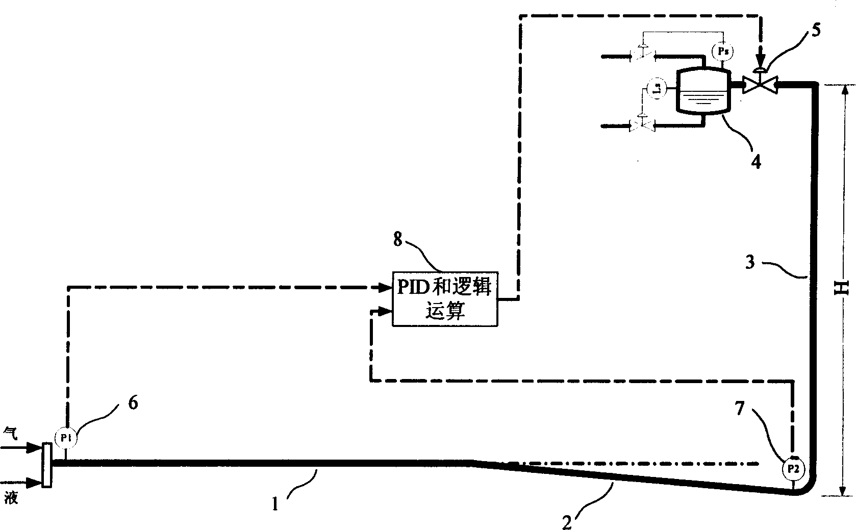
[0018] see figure 1 , the pressure sensor 6 set at the entrance of the incoming flow pipe 1 can output the signal of the pressure P1, the incoming flow pipe 1 is connected to the inclined pipe 2, and the pressure sensor 7 installed at the junction of the bottom of the rising pipe 3 and the inclined pipe 2 can output the pressure P2 The outlet of the rising pipe 3 is connected to the separator 4 through the automatic regulating valve 5, and the PID and logical operation control module 8 can receive the valve opening signal, the pressure P1 signal and the pressure P2 signal.

[0019] The parameter that can reflect the law of severe slug flow most quickly is the signal of the pressure P2 at the bottom of the riser 3, so in the present invention, the fluctuation amplitude and the average value of the pressure P2 signal at the bottom of the riser 3 are selected as the adj...


PUM


Abstract

The invention discloses a valve flow regulating control method for eliminating the serious plug flow sections. The automatic adjusting valve installed on the outlet of the ascending pipe, PID for receiving valve opening signal, inlet pressure signal and the pressure signal from the bottom of the ascending pipe, and logical algorithm control module can perform the dynamic control of the valve flow regulating. Analyzing, calculating and converting on the inlet pressure and pressure signal of the bottom of the ascending pipe and valve opening signal and outputting the signal to real time control the opening of the automatic adjusting valve, three threads calculating parallel can react to the pressure variation of long cycle and stable the regulating flow on a proper degree.

Description

technical field [0001] The invention belongs to the technical field of throttling dynamic feedback control, and relates to a valve throttling dynamic control method, in particular to a riser outlet throttling dynamic control method for eliminating serious slug flow phenomenon in the mixed transportation process of offshore oil and natural gas. Background technique [0002] In offshore oil exploitation, it is often encountered that gas and liquid are transported at the same time. When the multi-phase gathering and transportation pipeline on the seabed reaches the offshore platform or goes ashore, it needs to be connected with the riser. Under certain conditions, a special harmful flow pattern called severe slug flow will appear in the system composed of the gathering pipeline and the rising pipe. This flow pattern will produce a liquid plug several times the height of the rising pipe, Periodic changes in pressure, intermittent outflow of gas and liquid at the outlet of the ri...

Claims


Application Information

Patent Timeline
IPC IPC(8): F17D3/01
Inventor 郭烈锦王鑫张西民
Owner XI AN JIAOTONG UNIV
Why Eureka
Try Eureka