
Data transmission device and data transmission system

A data transmission and data technology, applied in the direction of digital transmission system, transmission system, data exchange network, etc., can solve the problems of increased cost of routing devices, increased processing burden, increased cost of communication equipment, etc.

Inactive Publication Date: 2005-11-23
NIPPON TELEGRAPH & TELEPHONE CORP
View PDF3 Cites 3 Cited by
  • Summary
  • Abstract
  • Description
  • Claims
  • Application Information

AI Technical Summary

Problems solved by technology

[0004] However, currently, with the provision of various services such as VPN (Virtual Private Network: Virtual Private Network) and VLAN (Virtual Local Area Network: Virtual Local Area Network) that are rapidly spreading, the tunneling technology required to transmit data efficiently within a single exchange Corresponding communication equipment is provided for each communication protocol that is different from each other, and there is a problem that the cost of communication equipment increases.
[0009] However, when this existing routing device attaches or replaces a label, it needs to add an exchange label to the data packet so that the received data packet can be exchanged in the routing device, and the exchange label must also be retrieved through the target address or label. Obtained, there is a problem of increased processing load
In addition, the cost of routing equipment increases due to the increase in processing load, which also leads to an increase in the cost of network construction.

Method used


Image

  • Data transmission device and data transmission system
  • Data transmission device and data transmission system
  • Data transmission device and data transmission system

Examples


no. 1 Embodiment approach

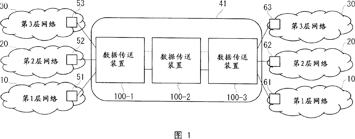
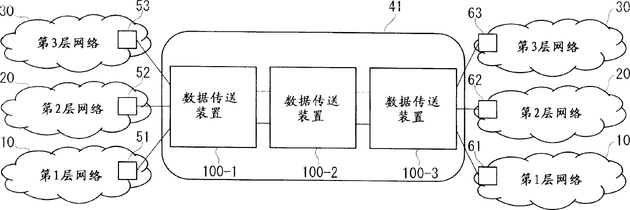
[0067] FIG. 1 is a block diagram showing a system configuration of a data transfer system according to a first embodiment of the present invention.

[0068] As shown in FIG. 1 , the configuration of the data transfer system 41 according to the present embodiment includes a plurality of data transfer devices 100 , but may also be composed of a single data transfer device 100 . In addition, the data transfer system 41 may constitute a backbone network connected to an external network composed of the first layer network 10 , the second layer network 20 , and the third layer network 30 .

[0069] The structure of the layer 1 network 10 includes an upstream data transmission device 51 and a downstream data transmission device 61 .

[0070] In addition, the so-called upstream data transmission device refers to a data transmission device that transmits received data when viewed from the perspective of a data transmission device that has received data. The so-called downstream data t...

no. 2 Embodiment approach

[0136] 4 is a block diagram showing a system configuration of a data transfer system according to a second embodiment of the present invention.

[0137] Although the data transmission system 42 of this embodiment includes a plurality of data transmission devices 100 and data transmission devices 200 in FIG. The data transmission device constitutes. In addition, the data transfer system 42 may constitute a backbone network connected to an external network constituted by the layer 1 network 10 , the layer 2 network 20 , and the layer 3 network 30 .

[0138] 5 is a block diagram showing a schematic configuration of a data transfer device according to a second embodiment of the present invention.

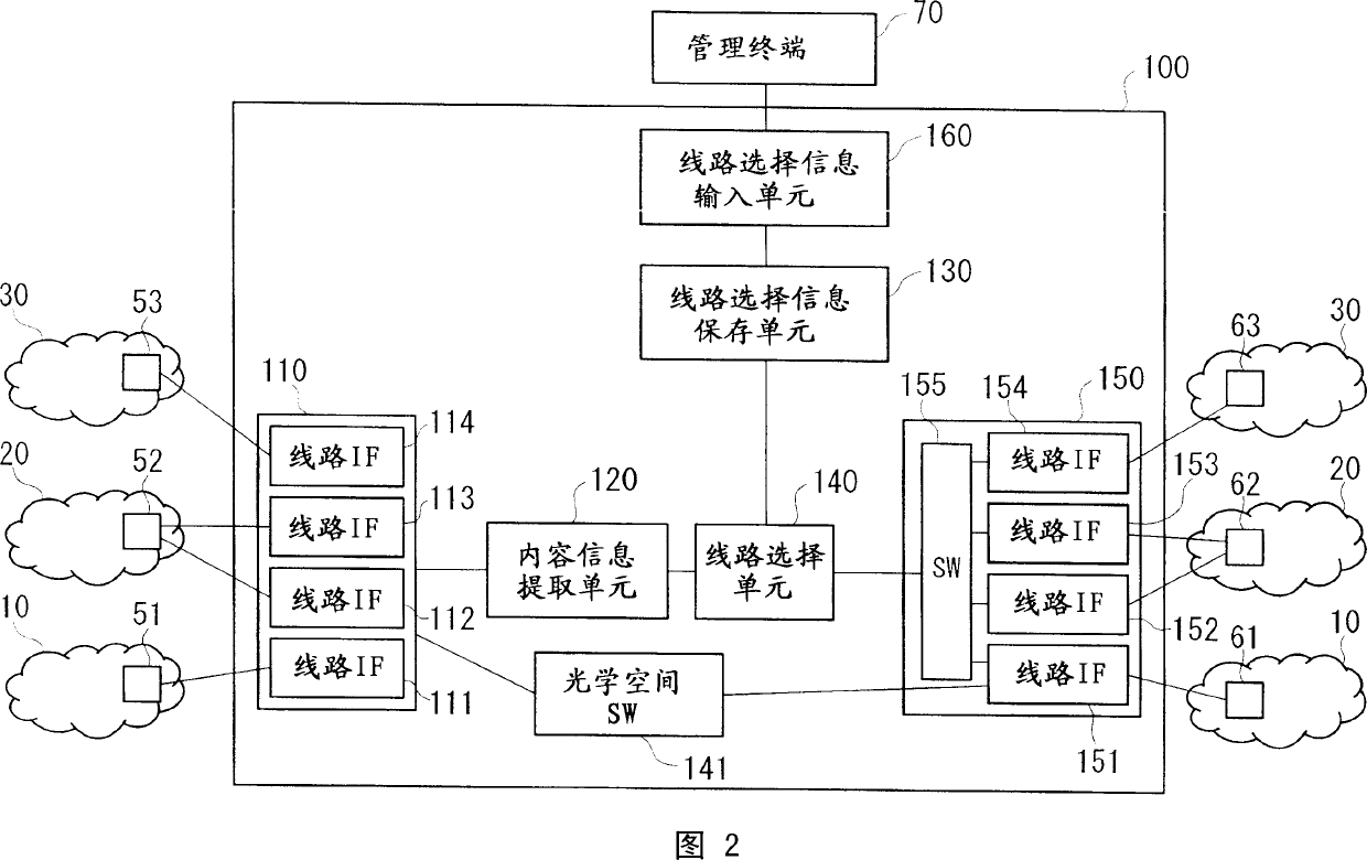
[0139] As shown in FIG. 5 , the data transmission device 200 of this embodiment includes: a data receiving unit 110, a content information extraction unit 120, a line selection information storage unit 130, a line selection unit 240, an optical space switch 141, a data transmission uni...

no. 3 Embodiment approach

[0163] FIG. 7 is a block diagram showing a system configuration of a data transfer system according to a third embodiment of the present invention.

[0164] Although the data transmission system 43 of this embodiment includes a plurality of data transmission devices 100 and data transmission devices 300 in FIG. The data transmission device constitutes. In addition, the data transfer system 43 may constitute a backbone network connected to an external network constituted by the layer-1 network 10 , the layer-2 network 20 , and the layer-3 network 30 .

[0165] 8 is a block diagram showing a schematic configuration of a data transfer device according to a third embodiment of the present invention.

[0166] As shown in FIG. 8 , the data transmission device 300 of this embodiment includes: a data receiving unit 110, a content information extraction unit 120, a line selection information storage unit 130, a line selection unit 240, an optical space switch 141, a data transmission ...


PUM


Abstract

A data transfer apparatus and a data transfer system are provided that can reduce the cost of installing communication equipment compatible with each of several dissimilar communication protocols in one exchange office and can reduce the cost of constructing the network. The data transfer apparatus includes a data reception device ( 110 ) that receives packets that comply with dissimilar communication protocols from upstream data transfer apparatuses ( 51, 52, and 53 ); a content data extraction device ( 120 ) that extracts content data included in the packets; a line selection information storage device ( 130 ) that stores the line selection information for selecting communication lines that comply with dissimilar communication protocols; a line selection device ( 140 ) that selects the communication line compatible with content data based on the line selection information; and a data transfer device ( 150 ) that transfers data to downstream data transfer apparatuses ( 61, 62, and 63 ) that are connected to the communication line that has been selected by the line selection device.

Description

technical field [0001] The invention relates to a data transmission device and a data transmission system for transmitting data, in particular to a data transmission device and a data transmission system following the network communication protocol. In addition, the present invention particularly relates to a device (hereinafter referred to as a routing device) and a network system for exchanging data packets conforming to the Internet Protocol (hereinafter referred to as IP packets) among data transfer devices, and when a network is constructed using a plurality of routing devices , an efficient technique for these routing devices. Background technique [0002] Among the existing data transmission devices, there is a data transmission device located at the edge of the network, which allocates different optical wavelengths to each target address contained in the IP packet, and time-division multiplexes the allocated optical wavelengths. By transmitting optical signals const...

Claims


Application Information

Patent Timeline
IPC IPC(8): H04L12/46H04L69/14
Inventor 桦岛启介青木道宏栗本崇宫村崇五岛正浩松浦伸昭漆谷重雄
Owner NIPPON TELEGRAPH & TELEPHONE CORP
Learn More