
Rod rounding machine cutter

A round bar machine and cutting tool technology, applied in the direction of rotary machines, manufacturing tools, rotary cutting tools, etc., can solve the problems of round bar fluffing and large cutting resistance, and reduce cutting resistance, improve production efficiency, and achieve high smoothness. Effect

Inactive Publication Date: 2005-12-14
梁志权
View PDF0 Cites 1 Cited by
  • Summary
  • Abstract
  • Description
  • Claims
  • Application Information

AI Technical Summary

Problems solved by technology

[0004] In order to overcome the disadvantages that the cutting edge of the cutter on the cutting device of the existing round bar machine is flat, the cutting resistance is large, and the appearance of the processed round bar is "fluffy", the invention provides a round bar machine tool

Method used


Image

  • Rod rounding machine cutter
  • Rod rounding machine cutter

Examples


Embodiment Construction

[0013] The present invention will be further described below in conjunction with the accompanying drawings and embodiments.

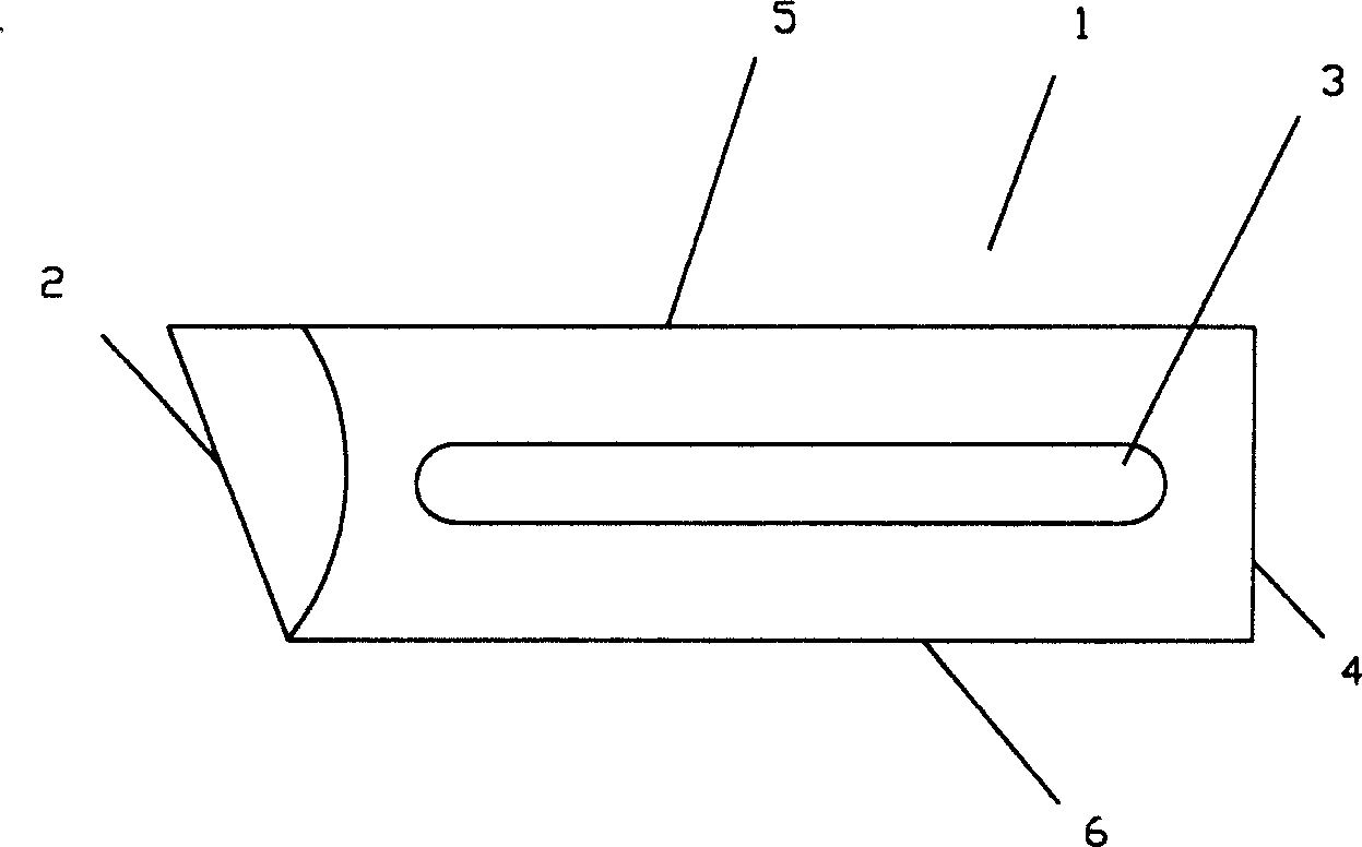
[0014] see figure 2 , figure 2 Shown is a structural diagram of the present invention, a round bar machine tool, including a tool body 1, the tool body 1 includes a knife edge 2, the knife edge 2 is an angled knife edge 2, the knife edge 2 and the tool body 1. The included angle in the parallel direction of the bottom surface is an acute angle. In this embodiment, the length of the long side 5 is 74mm, the length of the short side 6 is 52mm, and the length of the bottom surface 4 is 30mm; at the same time, the blade edge 2 is adjusted according to the difference in wood processing. acute angle.

[0015] The central portion of the tool body 1 is provided with an adjustment mounting hole 3, the cross-sectional shape of the adjustment mounting hole 3 is that the two ends are arc-shaped, and the middle part is a long strip shape. In this embodiment, the...


PUM


Abstract

The rod rounding machine cutter includes cutter body and angled edge formed through wire electrode cutting, and the edge is in an acute angle to the bottom plane of the cutter body. During cutting circular rod, the edge of the cutter has dot-line contact with the machined rod, and this results in less cutting resistance, raised production efficiency, and high smoothness of machined rod.

Description

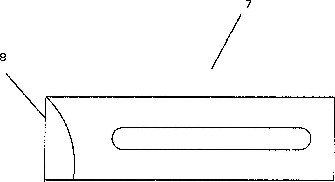
【Technical field】 [0001] The invention relates to a cutting tool, in particular to a cutting tool applied to a cutting device of a round bar machine in a woodworking machine. 【Background technique】 [0002] Round rod machine is a kind of woodworking machinery, it is mainly composed of machine base, cutting device, feeding roller, discharging roller and speed change device, it is mainly used for cutting wood round rods, and can also be used for cutting organic glass and hard rubber Round rods made of other materials are widely used in various craft factories and furniture factories due to the high quality and high production efficiency of the processed wood round rods. [0003] The cutting tool is an important part of the cutting device of the round bar machine, see figure 1 , the blade edge 8 of the existing cutter body 7 is all flat edges, that is, the blade portion is parallel to the bottom surface of the cutter body 7, such a cutter, when cutting a round rod, the contact...

Claims


Application Information

Patent Timeline
Patent Type & Authority Applications(China)
IPC IPC(8): B27G13/16
Inventor 梁志权
Owner 梁志权
Learn More