Vehicle brake device

A vehicle braking and braking force technology, which is applied in the direction of braking transmission, brakes, vehicle components, etc., can solve the problems of degradation of regenerative efficiency, inability to actively use regenerative braking force, and degradation of vehicle fuel efficiency, so as to improve energy efficiency , simplified structure, low cost effect

Inactive Publication Date: 2005-12-14
ADVICS CO LTD
View PDF5 Cites 37 Cited by
  • Summary
  • Abstract
  • Description
  • Claims
  • Application Information

AI Technical Summary

Problems solved by technology

[0009] However, in the vehicle brake device and the vehicle brake method described in the above-mentioned Patent Document 2, the braking force of the hydraulic brake device must be changed from the point of time when the brake pedal starts to be depressed to the time when the brake pedal is depressed. work between release time points
Thus, there is no room for the reg

Method used


Image

  • Vehicle brake device
  • Vehicle brake device
  • Vehicle brake device

Examples


no. 1 example

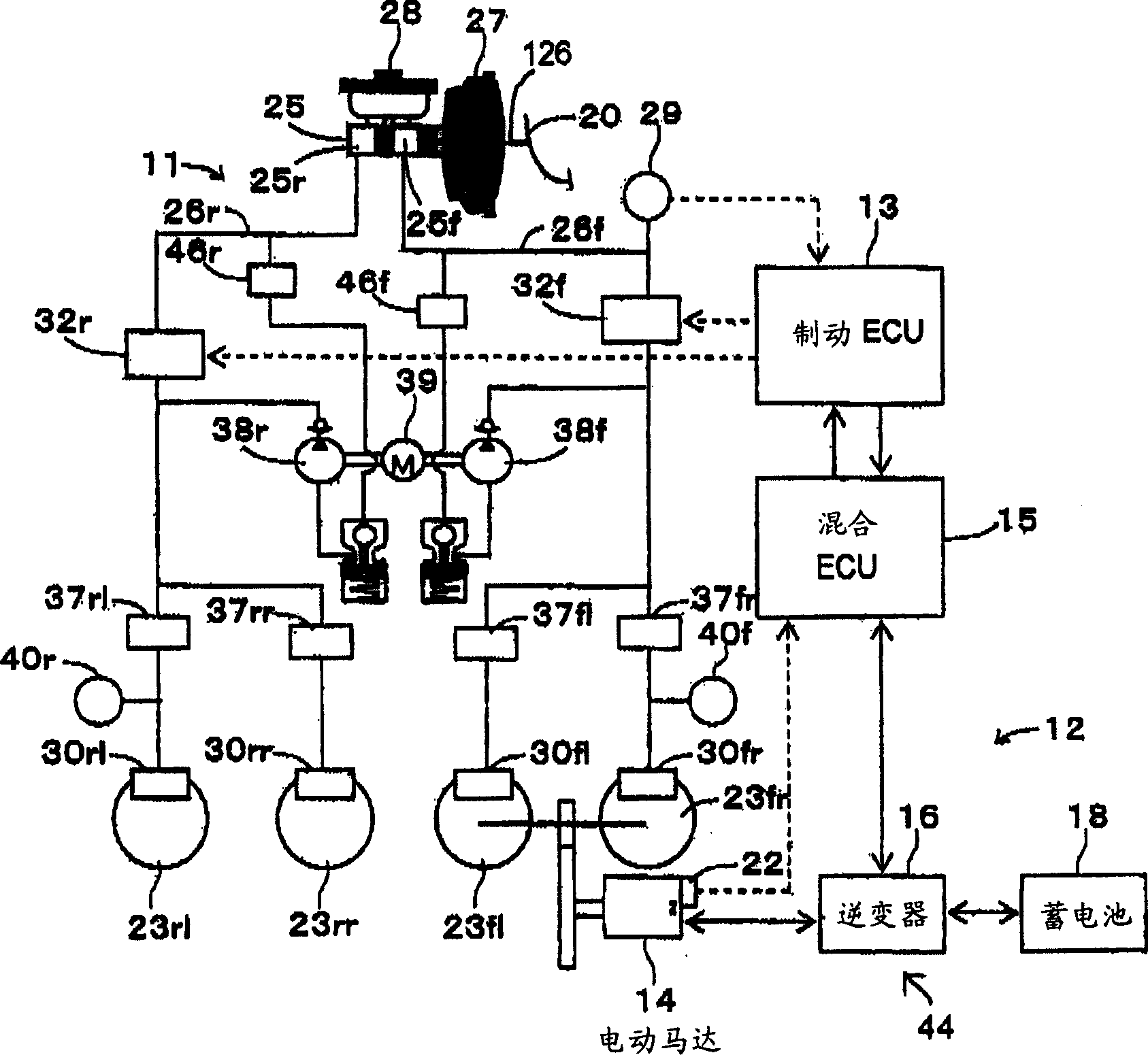
[0047] A vehicle braking device according to a first embodiment of the present invention will be described below with reference to the drawings. Such as figure 1 As shown in , the vehicle braking device is constructed to be applied to a front drive motor driven vehicle and is provided with a hydraulic braking device 11, a regenerative braking device 12, an ECU 13 for coordinating the control of these devices 11 and 12, and a 16 The hybrid ECU 15 controls the electric motor 14 which is the driving power source of the motor-driven vehicle according to the request value from the brake ECU 13 .

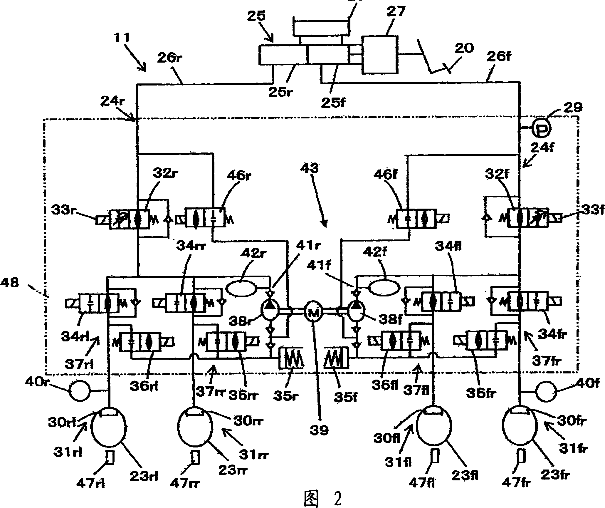
[0048] The hydraulic brake device 11 increases the brake operation force generated by the brake operation or the depression operation on the brake pedal 20 by making the vacuum booster 27 as a booster device increase, and by applying the brake force depending on the increase. The base fluid pressure of the steering force is applied to the sub-cylinders 30 of the wheels 23 , capable of ap...


PUM


Abstract

PROBLEM TO BE SOLVED: To increase the assignment proportion of a regeneration braking force to a target braking force in response to a braking operation force when the braking operation force is in a low region, and at the same time, to reduce the effect delayed feeling of the brake at the time of a sudden braking.

SOLUTION: When the braking operation force is in the low region, the boosting ratio of a booster becomes lower, and the assignment ratio of the regeneration braking force to the target braking force which is set to correspond to the braking operation force becomes higher, and an energy efficiency is increased. When the braking operation force exceeds the low region, the boosting ratio of the booster becomes higher, and an increasing ratio of a fundamental hydraulic pressure which is fed to a wheel cylinder from a master cylinder becomes larger. Therefore, even if a small delay occurs in the feeding of a control hydraulic pressure from the control hydraulic pressure braking force generating device at the time of a sudden braking, the braking means can generate a sufficiently large fundamental hydraulic pressure braking force on wheels.

COPYRIGHT: (C)2006,JPO&NCIPI

Description

[0001] This application claims Japanese Patent Application No. 2004-170309 filed on June 8, 2004, Japanese Patent Application No. 2004-174401 filed on June 11, 2004, Japanese Patent Application No. 2004 filed on September 30, 2004 .2004-285676, and foreign priority of Japanese Patent Application No. 2004-367601 filed on December 20, 2004. technical field [0002] The present invention relates to a vehicle braking device in which a target regenerative braking force to be applied to a wheel depending on a braking operation state is obtained by adding a hydraulic braking force of a hydraulic braking device and a regenerative braking force of a regenerative braking device. Background technique [0003] Hitherto, as described in Japanese Unexamined Published Patent Application 2002-264975 (hereinafter referred to as Patent Document 1), there is known a vehicle hydraulic brake device which is simple in structure, inexpensive and suitable for use in electric vehicles Performs regen...

Claims


Application Information

Patent Timeline
IPC IPC(8): B60T8/17B60T8/00B60T13/16B60T13/20
Inventor 牧一哉松浦正裕齐藤滋小久保浩一仙石裕二
Owner ADVICS CO LTD
Why Eureka
Try Eureka