Supersonic cleaning fixture

A technology of ultrasonic cleaning and fixtures, applied in cleaning methods and utensils, cleaning methods using liquids, chemical instruments and methods, etc., can solve the problems of metal surface peeling off, easy to be blocked, inconvenient disassembly and assembly, and achieve the effect of reducing adsorption

Inactive Publication Date: 2005-12-21
SHANGHAI INST OF OPTICS & FINE MECHANICS CHINESE ACAD OF SCI
View PDF1 Cites 16 Cited by
  • Summary
  • Abstract
  • Description
  • Claims
  • Application Information

AI Technical Summary

Problems solved by technology

But at the same time, we also found the following shortcomings in the experiment: first, it is inconvenient to disassemble and assemble when more than three workpieces are clamped; second, glass substrates of different sizes cannot be cleaned at the same time; third, the sliding frame is in four Simultaneous sliding on the slide bar is easily blocked, causing inconvenience during disassembly, and it is easy to rub against the slide bar to cause the metal surface to fall off and pollute the cleaning solution; fourth, different workpieces cannot be cleaned at one time according to different cleaning times. It can be installed and disassembled at the same time; fifth, the fastening structure in which the screws used in the whole set of fixtures are vertically attached to the metal frame is also prone to contamination of the cleaning solution by metal debris due to the mutual friction between the screws and the frame during fastening

Method used


Image

  • Supersonic cleaning fixture
  • Supersonic cleaning fixture
  • Supersonic cleaning fixture

Examples


Embodiment Construction

[0018] The ultrasonic cleaning fixture of the present invention will be further described below in conjunction with the examples, but the scope of protection of the present invention should not be limited by this.

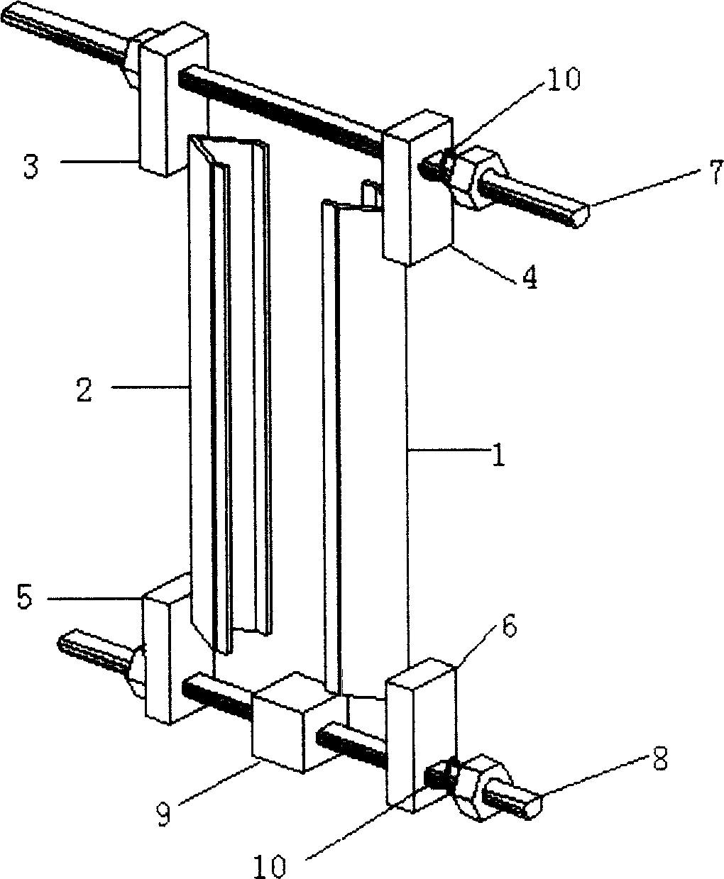
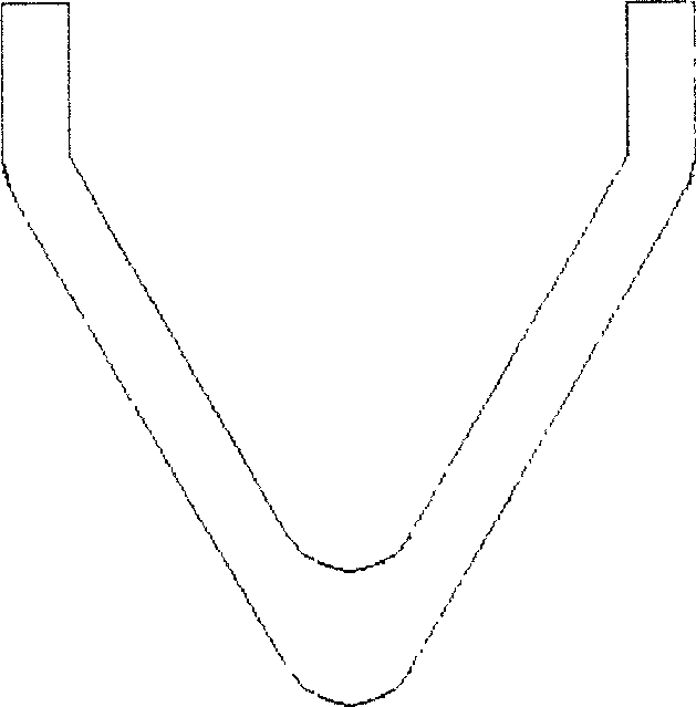
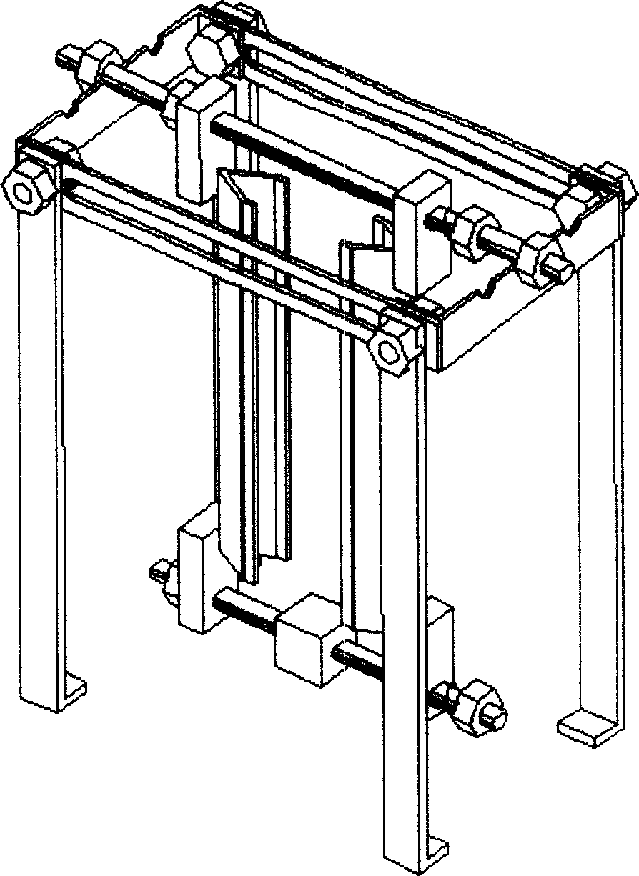
[0019] see first figure 1 and figure 2 , figure 1 It is a structural schematic diagram of an embodiment of the ultrasonic cleaning jig of the present invention. It can be seen from the figure that an ultrasonic cleaning fixture of the present invention is composed of: the first triangular clamp arm 1 and its upper block 4 and lower block 6 are fixed together; the second triangular clamp arm 2 and its upper block 3 and lower block 5 fixed together; the upper block and the lower block shown are provided with corresponding through holes; a long upper positioning screw 7 and a short lower positioning screw 8, and the lower positioning screw 8 passes through the fastening nut in turn screw hole, buffer spring 10, the through hole of block 6 under the first triangula...


PUM


Abstract

This present invention relates to a ultrasonic cleanout equipment. It can be applied to glass before filming ultrasonic cleanout which demands high lustration and the other industrial ultrasonic cleanout. The characters of it is that a below orientation screw drills through the nut, amortizing spring, diamonds below the first and third interlayer, the screw of leading flow diamonds, the diamonds below the second and the third interlayer and the fixed nut in turn. Another top orientation drills through nut, amortizing spring, diamonds above the first and the third interlayer, diamonds above the second and the third interlayer and fixed nut in turn. The frame of this present invention is simple and credible, flexible to use.

Description

technical field [0001] The invention relates to coating, in particular to an ultrasonic cleaning jig used for ultrasonic cleaning of substrates such as glass before coating with high cleanliness requirements and other industrial ultrasonic cleaning. technical background [0002] With the development of high-power laser technology, in the laser system, more and more requirements are put forward for the anti-laser damage ability of various related optical films, and the coating technology of optical films is also required to be refined. There are generally two ways to clean glass or other material coating substrates and workpieces before coating, namely manual scrubbing and ultrasonic cleaning. Manual scrubbing is inefficient and cannot achieve large-scale high-efficiency production, and it is easy to cause artificial damage to the processed workpiece. Ultrasonic cleaning overcomes the above shortcomings, and is widely used for its simple operation, high cleaning efficiency a...

Claims


Application Information

Patent Timeline
Patent Type & Authority Applications(China)
IPC IPC(8): B08B3/12
Inventor 王成仁孙荣阁易葵贺洪波
Owner SHANGHAI INST OF OPTICS & FINE MECHANICS CHINESE ACAD OF SCI
Why Eureka
Try Eureka