Apparatus including an electroacoustic transducer having terminal contacts which extend in the direction of the transducer axis and including a printed circuit board having mating contacts

A printed circuit board and converter technology, which is applied in the directions of printed circuits, printed circuits, and circuit lead arrangement/elimination where non-printed electrical components are connected, can solve problems such as inability to use converters, and achieve a small and simple overall height. method, the effect of easy installation

Inactive Publication Date: 2004-07-21
KNOWLES ELECTRONICS ASIA
View PDF1 Cites 0 Cited by
  • Summary
  • Abstract
  • Description
  • Claims
  • Application Information

AI Technical Summary

Problems solved by technology

However, a further miniaturization of the above-mentioned known device and the above-mentioned acoustic-electric transducer causes problems because of the mating contact element formed by the terminal contact element with a bent contact spring and the conductive track area on the printed circuit board A normal conductive connection can only be established if the structure of the housing and the structure of the printed circuit board lie within relatively narrow tolerance limits, since the contact element with a bent terminal can only compensate the tolerances in the above-mentioned structure to a limited extent
It should also be noted that the above-mentioned terminal contact element composed of a curved contact spring provided by the patent document WO98 / 38832 A1 can only be miniaturized to a limited extent, and thus cannot be compared with existing converters. Further miniaturized converters are used in

Method used


Image

  • Apparatus including an electroacoustic transducer having terminal contacts which extend in the direction of the transducer axis and including a printed circuit board having mating contacts
  • Apparatus including an electroacoustic transducer having terminal contacts which extend in the direction of the transducer axis and including a printed circuit board having mating contacts
  • Apparatus including an electroacoustic transducer having terminal contacts which extend in the direction of the transducer axis and including a printed circuit board having mating contacts

Examples


Embodiment Construction

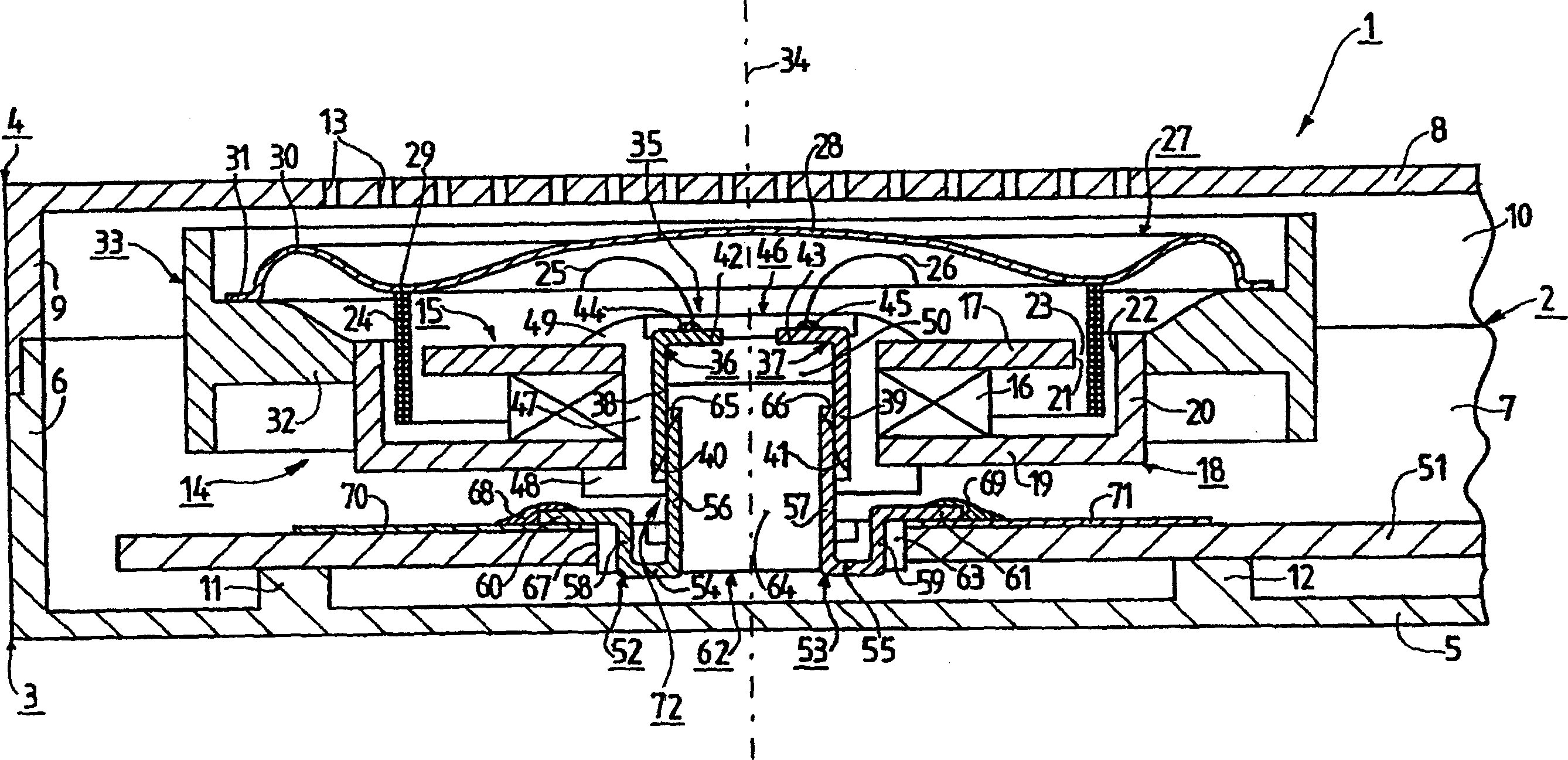
[0039] figure 1 The shown device 1 is, for example, a mobile phone. The device 1 has a housing 2 formed from a first half shell 3 and a second half shell 4 . exist figure 1 The bottom wall 5 of the first half-shell 3 , a short side wall 6 and a long side wall 7 are shown in . figure 1 The top wall 8 of the second half-shell 4, a short side wall 9 and a long side wall 10 are also shown in FIG. There are two ribs 11 and 12 on the bottom wall 5, the functions of which will be described in detail below. The top wall 8 has many sound transmission holes 13 .

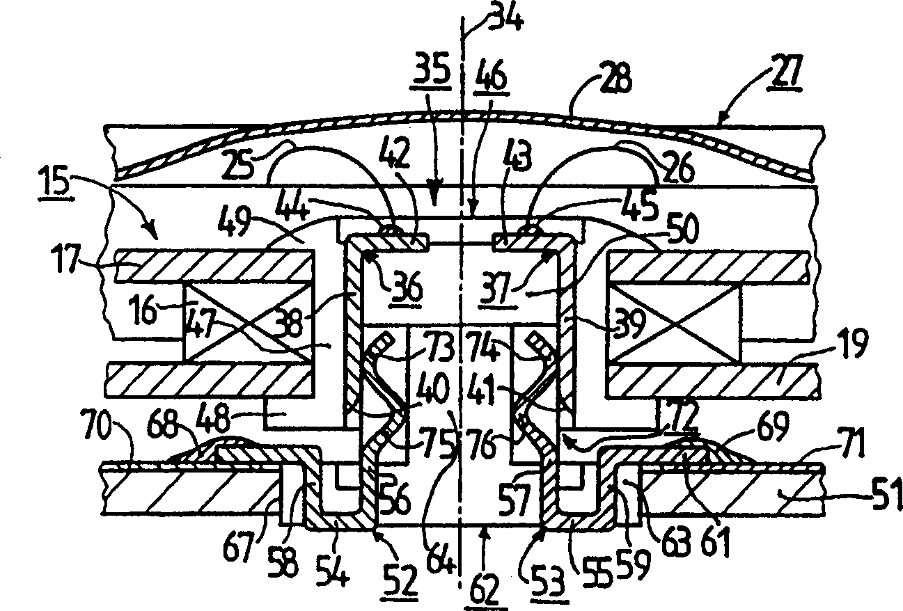
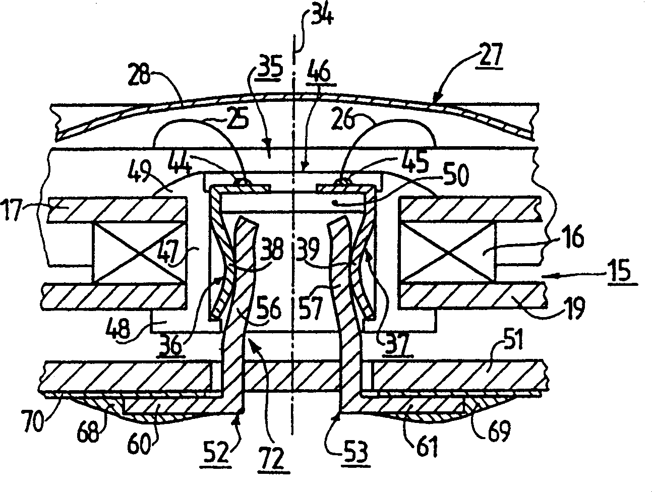
[0040] The housing 2 accommodates an acoustic-electric transducer 14 . The acoustic-electric transducer 14 is an electrodynamic loudspeaker. The converter 14 has a magnetic circuit system 15 comprising a magnet 16, an annular first choke 17 called a pole plate and a pot-shaped second choke 18 formed by an annular bottom 19 and A hollow cylindrical peripheral portion 20 constitutes. An air gap 23 is formed between the p...


PUM


Abstract

In an apparatus (1) having an electroacoustic transducer (14) and having a printed circuit board (51) the electroacoustic transducer (14) has two terminal contact elements (36, 37) and the printed circuit board (51) has two mating contact elements (52, 53), which terminal contact elements (36, 37) have two terminal contact portions (38, 39) which are oriented parallel to the transducer axis (34) of the transducer (14) and which mating contact elements (52, 53) have two mating contact portions (56, 57) which are oriented parallel to the transducer axis (34), the terminal contact portions (38, 39) and the mating contact portions (56, 57) being held pairwise against each other in a direction transverse to the transducer axis (34) and thus forming at least parts of a retainer (72) with the aid of which the transducer (14) is secured to the printed circuit board (51).

Description

technical field [0001] The invention relates to a device having a housing and an acoustic-electric transducer accommodated in the housing. [0002] The invention also relates to an acoustic-electric transducer. Background technique [0003] Devices having a housing and an acoustic-electric transducer housed in the housing and the acoustic-electric transducer have been widely used and are known. For this known structure, reference can be made to patent document WO98 / 38832 A1. According to the patent document WO 98 / 38832 A1, the known construction of such an acoustic-electric transducer can be fastened to the housing of a known device by means of a fastening device. The printed circuit board is then also fastened to the housing or connected to a stationary part of the housing by means of other fastening means. The terminal contact element is formed with a bent contact spring. The mating contact elements are formed by areas of conductive traces on the printed circuit board....

Claims


Application Information

Patent Timeline
Patent Type & Authority Patents(China)
IPC IPC(8): H04R9/02H04R1/06H04R7/12H04R9/06H05K1/18
CPCH04R9/025H05K1/182H04R9/06
Inventor P·布雷姆E·弗拉斯E·克雷恩E·鲁伯尔
Owner KNOWLES ELECTRONICS ASIA
Why Eureka
Try Eureka