Impedance calibration circuit and method
An impedance correction and circuit technology, applied in impedance networks, electrical components, networks using active components, etc., and can solve problems such as changes in the characteristics of active components, changes, and the influence of circuit operation.
- Summary
- Abstract
- Description
- Claims
- Application Information
AI Technical Summary
Problems solved by technology
Method used
Image

Examples
Embodiment Construction
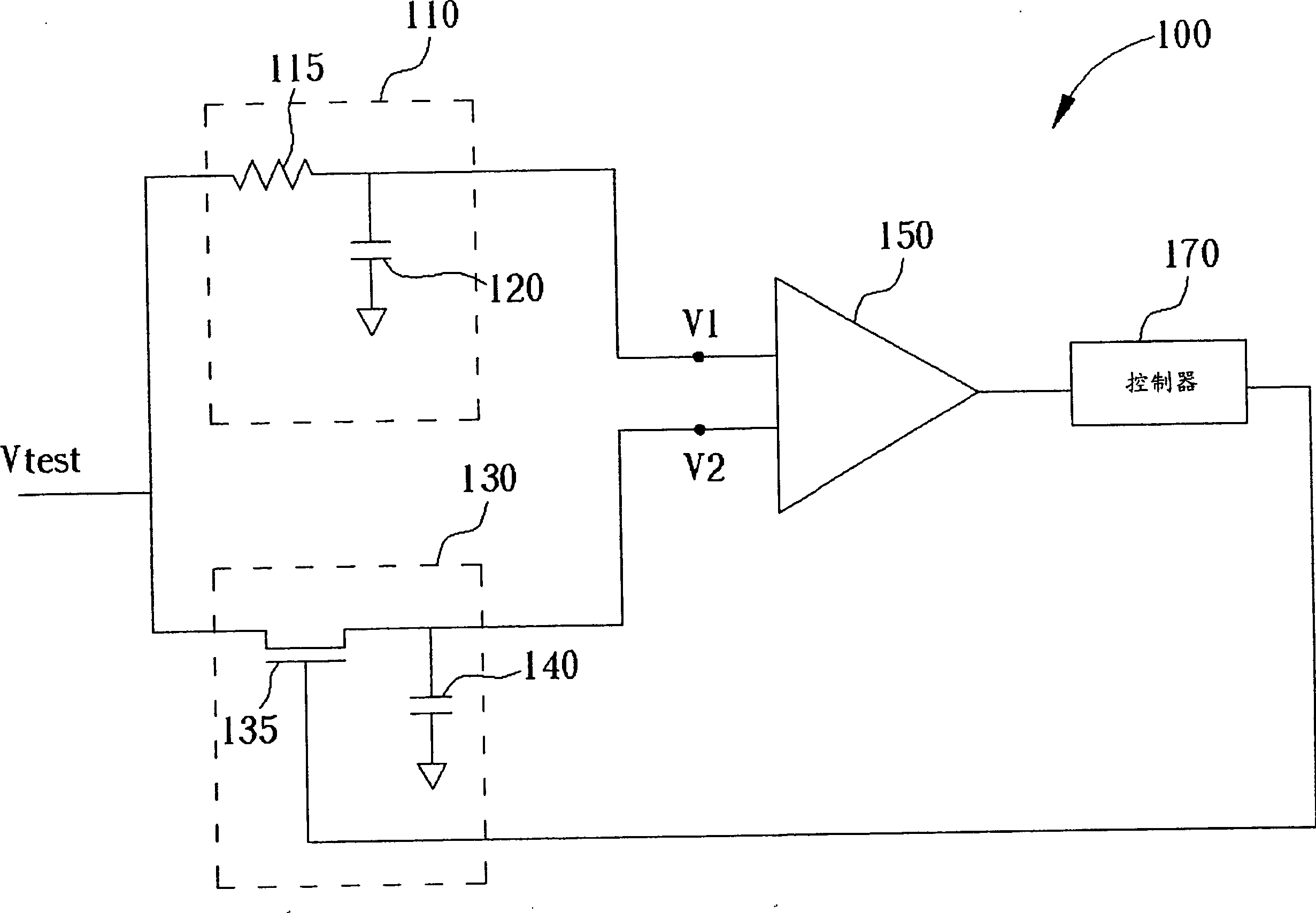
[0019] See figure 1 , figure 1 It is a schematic diagram of the first embodiment of the impedance correction circuit of the present invention. figure 1 The impedance correction circuit 100 is used to correct the equivalent impedance of the semiconductor element 135. In this embodiment, the semiconductor element 135 is a MOS transistor. The impedance correction circuit 100 includes a reference circuit 110 composed of a reference element 115 and a first capacitor 120; a second capacitor 140 in which the semiconductor element 135 and the second capacitor 140 constitute a test circuit 130; and a comparator 150; And a controller 170. Those skilled in the art should understand that the parameter control of the semiconductor capacitor in the manufacturing technology is relatively accurate. Therefore, in this embodiment, the first capacitor 120 and the second capacitor 140 are designed to have the same capacitance value.
[0020] To calibrate the equivalent impedance of the semiconduct...
PUM
 Abstract
Description
Claims
Application Information
 - R&D
- Intellectual Property
- Life Sciences
- Materials
- Tech Scout
- Unparalleled Data Quality
- Higher Quality Content
- 60% Fewer Hallucinations
Browse by: Latest US Patents, China's latest patents, Technical Efficacy Thesaurus, Application Domain, Technology Topic, Popular Technical Reports.
© 2025 PatSnap. All rights reserved.Legal|Privacy policy|Modern Slavery Act Transparency Statement|Sitemap|About US| Contact US: help@patsnap.com