Electronic parts mounting apparatus and method

An electronic component installation and electronic component technology, applied in the direction of electrical components, electrical components, measuring devices, etc., can solve problems such as changes in component installation accuracy, and achieve the effect of ensuring component installation accuracy

Inactive Publication Date: 2005-12-21
PANASONIC CORP
View PDF1 Cites 11 Cited by
  • Summary
  • Abstract
  • Description
  • Claims
  • Application Information

AI Technical Summary

Problems solved by technology

Therefore, when a component mounting operation is performed by selecting a recognition system according to a recognized object in such an electronic component mounting apparatus that selectively uses a plurality of recognition systems, the difference in position recognition results as described causes component mounting Variation in Accuracy

Method used


Image

  • Electronic parts mounting apparatus and method
  • Electronic parts mounting apparatus and method
  • Electronic parts mounting apparatus and method

Examples


Embodiment Construction

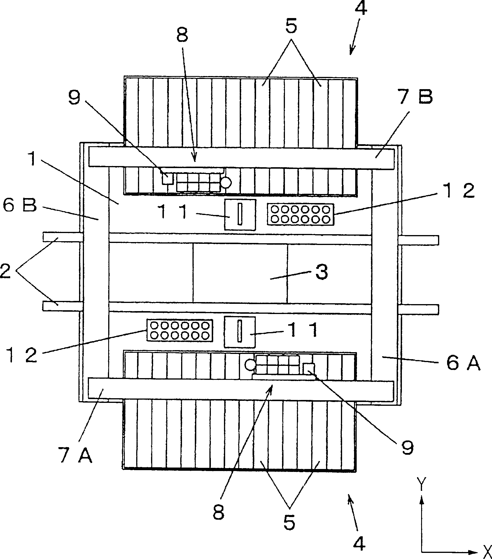
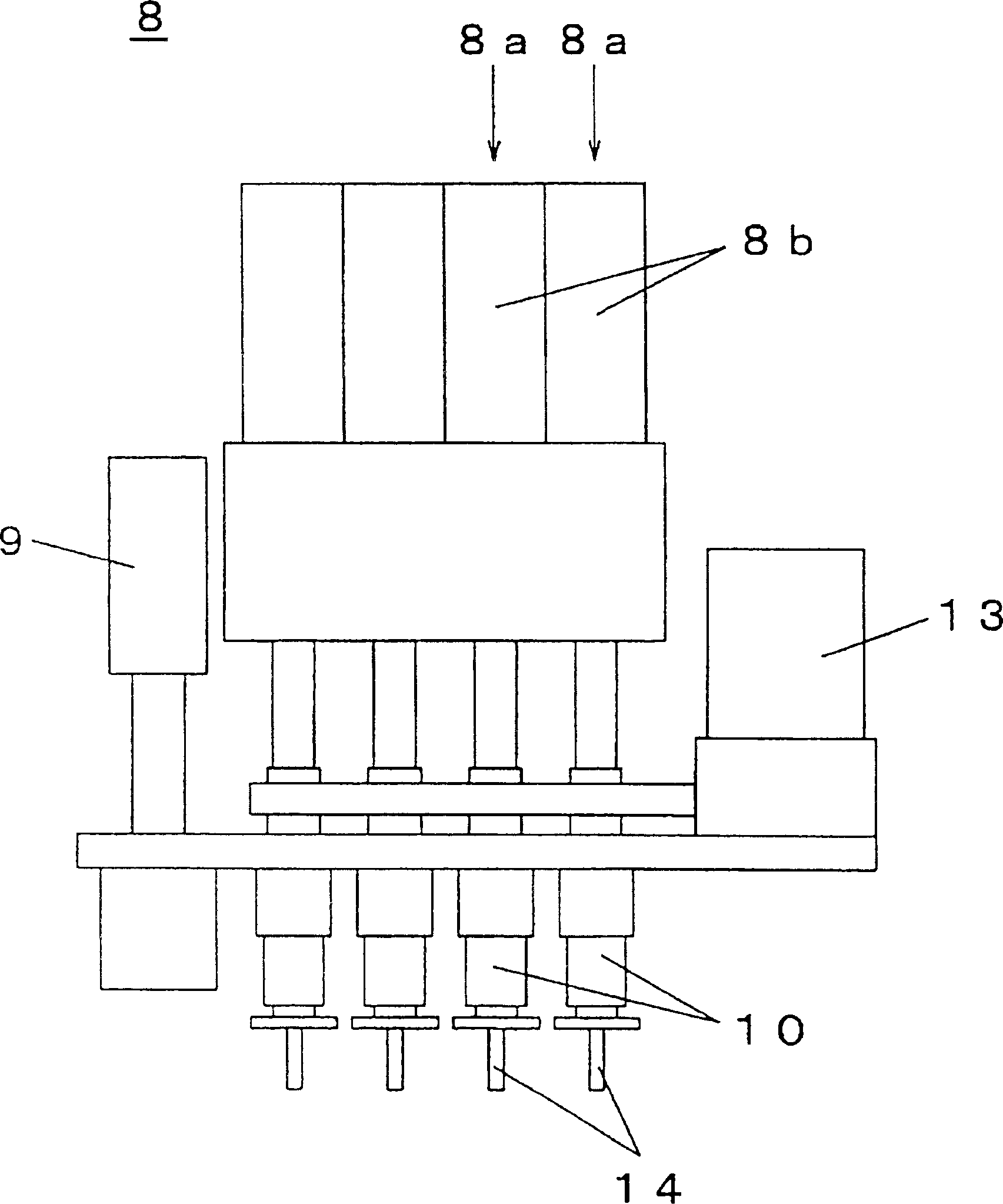
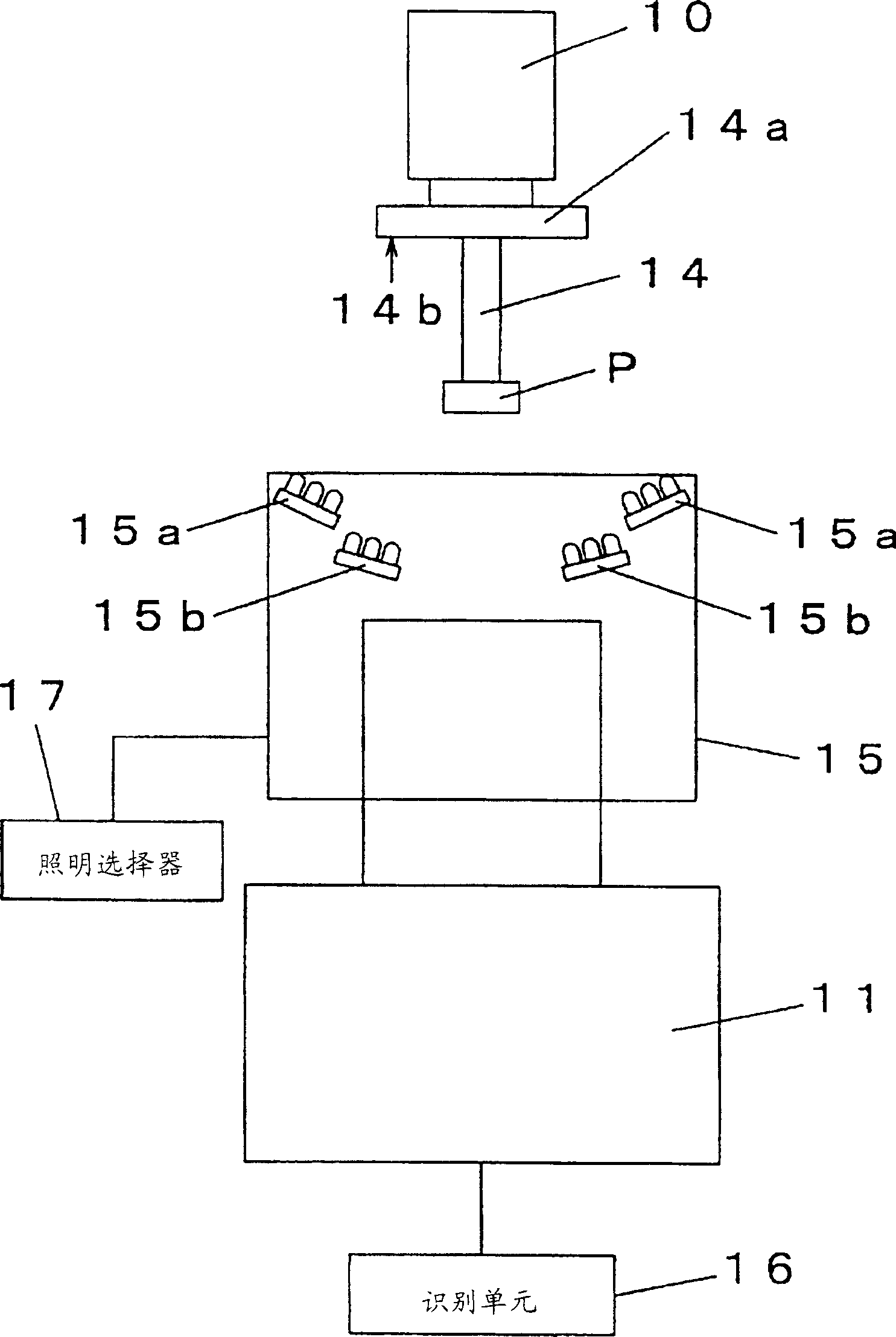
[0017] Preferred embodiments of the present invention will be described below with reference to the accompanying drawings. figure 1 It is a plan view showing an electronic component mounting device according to an embodiment of the present invention. figure 2 yes means figure 1 Schematic diagram of the transfer head unit of the electronic component mounting equipment in . image 3 is expressed in figure 1 An explanatory view of the image recognition device used in the electronic component mounting equipment of . Figure 4A and 4B is explained in figure 1 An explanatory view of component recognition processing in electronic component mounting equipment. Figure 5 is displayed on figure 1 Block diagram of the control system of the electronic component mounting equipment. Image 6 is displayed by figure 1 A flowchart of the flow of the electronic component mounting process performed by the electronic component mounting equipment.

[0018] will refer to figure 1 Describ...


PUM


Abstract

An electronic component mounting apparatus which uses a mounting head to hold an electronic component, takes a picture of the electronic component by a line camera (11), processes the image of the electronic component taken by the line camera, and identifies the electronic component by using a recognition unit (16) position, positioning the electronic component on the substrate according to the position recognition result, and mounting the electronic component on the substrate. The pre-stored offset for each identification system with its own light source is used for positioning when correcting the position according to the position of the identification result, wherein the light source is a light source for transmitted illumination (15a) or Light source (15b) for reflected lighting. Even in such an electronic component mounting apparatus that selectively uses a plurality of recognition systems, differences in position recognition results caused by use of other types of lighting methods are corrected to secure necessary component mounting accuracy.

Description

technical field [0001] The present invention relates to an electronic component mounting apparatus and method for holding an electronic component with a nozzle, transferring the electronic component thus held onto a substrate, and mounting the electronic component on the substrate. Background technique [0002] In such an apparatus for mounting electronic components on a substrate, a technique of correcting the mounting position of the electronic component by using image recognition processing is widely used to improve the accuracy of the mounting position of the electronic component on the substrate. In this technique, a transfer head picks up an electronic component from a component supply section, holds the electronic component with a nozzle, and then moves along a path to a substrate. The camera photographs the electronic components held by the head. The captured image of the electronic component is processed for detecting deflection of the electronic component. When t...

Claims


Application Information

Patent Timeline
Patent Type & Authority Applications(China)
IPC IPC(8): G01B11/03H05K13/04
CPCH05K13/0452H05K13/0812Y10T29/53261Y10T29/53178Y10T29/53174Y10T29/53191H05K13/04
Inventor 永尾和英吉冨成之
Owner PANASONIC CORP
Why Eureka
Try Eureka