Eccentric fan and air conditioner therewith

A centrifugal fan and fan blade technology is applied in air conditioning systems, components and applications of elastic fluid pumping devices, and can solve problems such as rising costs and work burdens, increasing the number of components, and increasing exhaust sound. , to achieve the effect of suppressing wasteful power loss, reducing eddy current noise, and suppressing the increase of wing end eddy current

Inactive Publication Date: 2005-12-28
SAMSUNG ELECTRONICS CO LTD
View PDF1 Cites 13 Cited by
  • Summary
  • Abstract
  • Description
  • Claims
  • Application Information

AI Technical Summary

Problems solved by technology

That is, the adoption of the shroud-attached structure not only increases the number of parts, but also requires the process of joining the shrouds in addition to forming the shrouds separately for the main board and the blades, which has the problem of greatly increasing the cost and workload.
[0008] In addition, the structure of setting the guard plate close to the fan wing is as follows: Figure 12 As shown, because the overflow flow T on the upstream side of the fan blade 104 interferes with the guard plate 131 ( Figure 12 The conflict U) increases the exhaust sound, resulting in a decrease in merchandise

Method used


Image

  • Eccentric fan and air conditioner therewith
  • Eccentric fan and air conditioner therewith
  • Eccentric fan and air conditioner therewith

Examples


Embodiment Construction

[0045] The centrifugal fan provided by the embodiment of the present invention and the air conditioner using the fan will be described below with reference to the accompanying drawings.

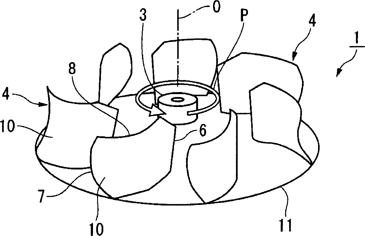
[0046] figure 1 It is a perspective view of the centrifugal fan provided by the first embodiment of the present invention. As shown in the figure, the centrifugal fan 1 of this embodiment has: a roughly disk-shaped main board 11 that rotates in a predetermined direction P (counterclockwise) around the rotating shaft O; O uniformly arranged slightly cylindrical hub 3; a plurality of fan wings 4 arranged on the outer peripheral side of the hub 3.

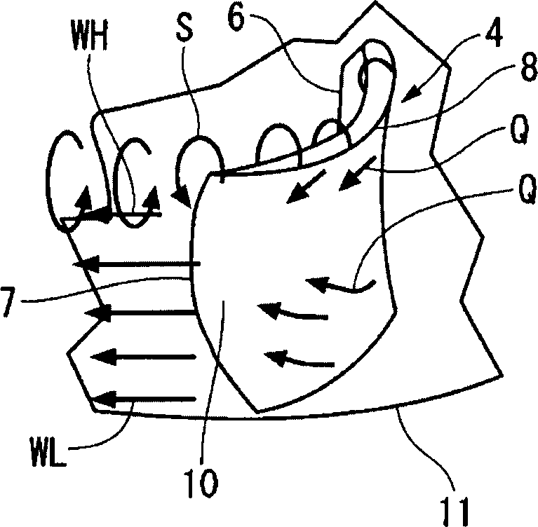
[0047] For the fan wing 4 refer to figure 2 be explained. figure 2 to press figure 1 The oblique view of the blade 4 of the centrifugal fan shown. As shown in the figure, the fan wing 4 is designed to stand up from the main board 11 and extend from the inside to the outside in the radial direction of the main board 11, and is arranged on the...


PUM


Abstract

PROBLEM TO BE SOLVED: To provide a centrifugal fan capable of increasing marketability by suppressing noise while reducing cost, and an air conditioner using the centrifugal fan. SOLUTION: This centrifugal fan comprises a main plate 11 rotatable in a prescribed direction P around a rotating axis O and vanes 4 disposed on the main plate 11. The cross sections of the vanes 4 at the same radial position of the main plate 11 including at least the trailing edge 7 positioned on the outer peripheral side of the main plate 11 are curved to be projected in the anti-rotating direction (-P direction) of the main plate 11. The curve is gradually increased from the leading edge 6 to the trailing edge 7 of the vanes 4. COPYRIGHT: (C)2006,JPO&NCIPI

Description

technical field [0001] The present invention relates to a centrifugal fan and an air conditioner using the fan. The fan has a main board rotatable in a predetermined direction around a rotating shaft and fan wings arranged on the main board. Background technique [0002] As the most basic type of centrifugal fan, such as Figure 6 The examples shown are well known. The centrifugal fan 101 shown in this figure has a hub 103 , a main plate 111 with one end of the hub 103 aligned with the rotation axis, and blades (fan blades) 104 provided on the main plate 111 . A bell mouth 108 and a guard plate 109 placed on the upper end side of the fan wing 104 are provided above. [0003] This kind of centrifugal fan 101 rotates the hub 103 in a predetermined direction P (counterclockwise) to make the fan blades 104 rotate accordingly, so that fluid (such as air) flows into the centrifugal fan through the opening of the bell mouth 108 as shown by the arrow M. T...

Claims


Application Information

Patent Timeline
Patent Type & Authority Applications(China)
IPC IPC(8): F04D29/28F04D29/30F04D29/38F04D29/66F24F1/00
CPCF04D29/026F04D29/281F04D29/30F04D29/663F04D29/667F05D2210/12Y10S415/00Y10S416/00Y10S417/00
Inventor 多久岛朗
Owner SAMSUNG ELECTRONICS CO LTD
Why Eureka
Try Eureka