Electronic component mounting apparatus and electronic component mounting method

A technology for installing and comparing devices for electronic components, applied in the direction of electrical components, electrical components, etc., can solve the problems of printed circuit board installation position offset, positioning instability, etc.

Inactive Publication Date: 2005-12-28
HITACHI HIGH TECH INSTR CO LTD
View PDF1 Cites 10 Cited by
  • Summary
  • Abstract
  • Description
  • Claims
  • Application Information

AI Technical Summary

Problems solved by technology

[0004] However, when there is a mistake in the process schedule change of the positioning part of the positioning board, the positioning is unstable. In addition, when positioning the printed circuit board in a bent state (for example, an upper bent state), since the electronic components are mounted after the board position recognition, Therefore, the printed circuit board is installed in an unstable state, or the upper bending state during positioning is installed in a horizontal state, so the installation position of the printed circuit board is shifted.

Method used


Image

  • Electronic component mounting apparatus and electronic component mounting method
  • Electronic component mounting apparatus and electronic component mounting method
  • Electronic component mounting apparatus and electronic component mounting method

Examples


Embodiment Construction

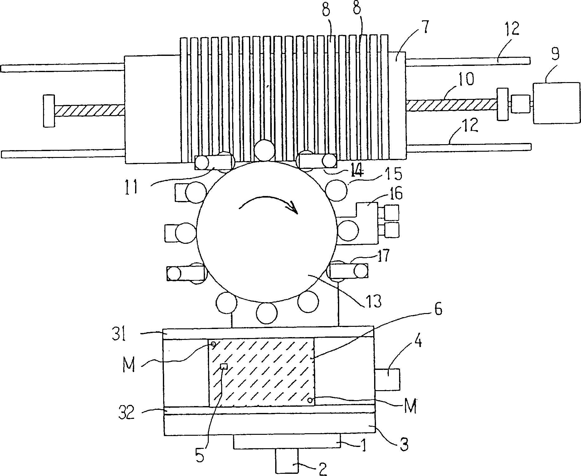
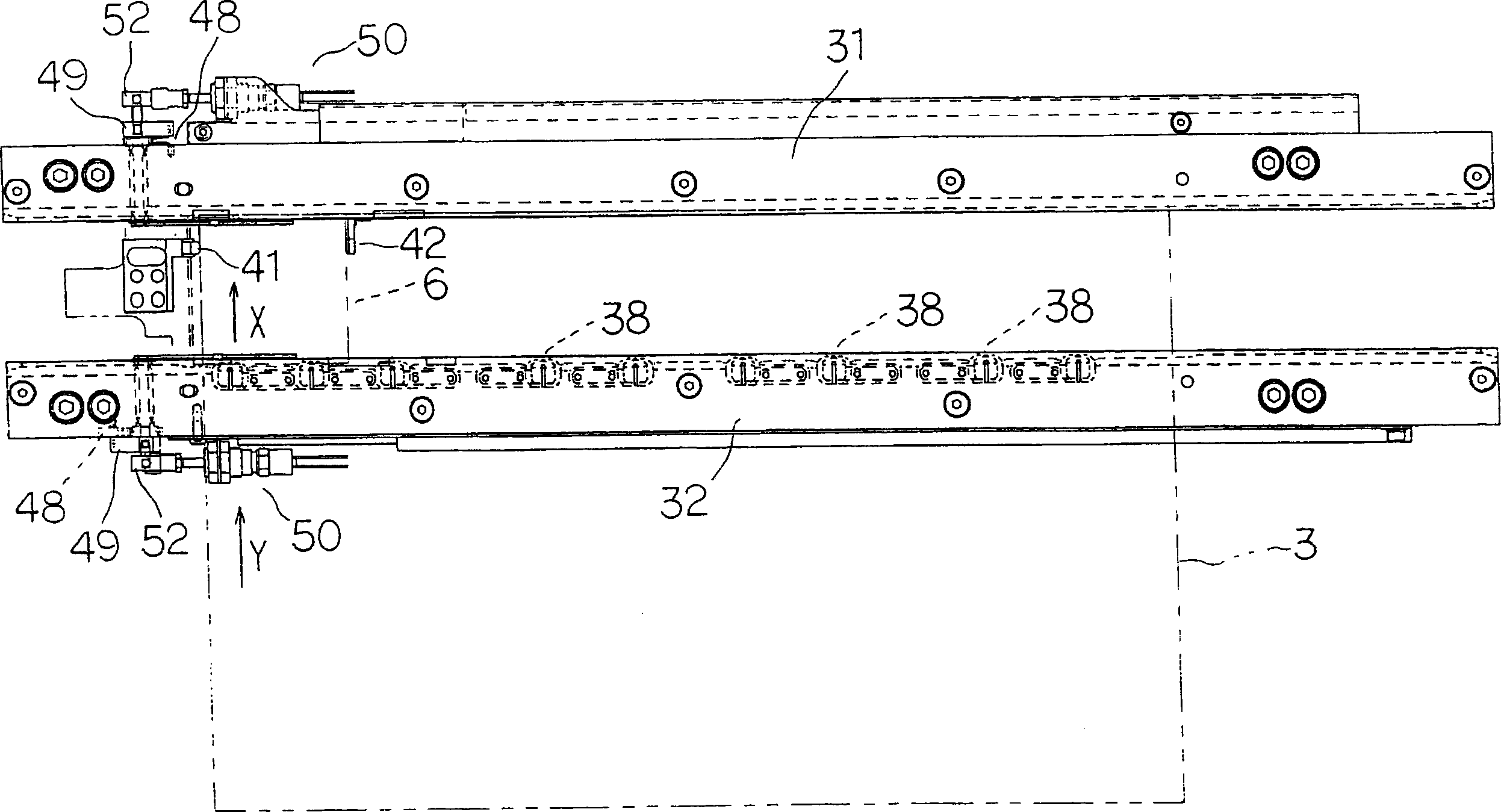
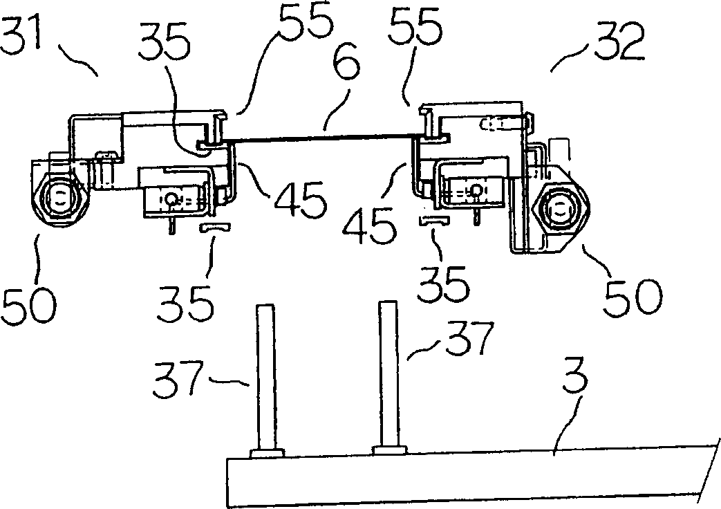
[0031] Hereinafter, an embodiment of an electronic component mounting apparatus for mounting chip electronic components on a printed wiring board will be described in detail with reference to the drawings. Number 1 is the Y stage that moves in the Y direction by the rotation of the Y-axis drive motor 2, and number 3 is the Y stage 1 that moves in the X direction by using the rotation of the X-axis drive motor 4, and finally moves in the XY direction. On the XY mounting table, the printed circuit board 6 on which the chip electronic components 5 (hereinafter referred to as "chip components" or "components") are mounted is fixed by a fixing device not shown, and placed on a pair of conveying slides 31 and 32.

[0032]Numeral 7 is a supply stand, and a plurality of component supply units 8 for supplying sheet components 5 are arranged. Numeral 9 is the supply table driving motor. By rotating the round head bolt 10, the supply table 7 is guided to the supply table 7 on the straight gu...


PUM


Abstract

An electronic component mounting device and an electronic component mounting method. The position recognition of the printed wiring board is carried out before and after the chip component is mounted, and when the front and rear deviation is outside a certain range, the printed wiring board is treated as a defective product. CPU (61) compares the recognition position after installation and the recognition position before installation of each positioning mark M attached to the printed circuit board (6) that is photographed by the substrate recognition camera (70) and recognized and processed by the recognition processing device (68) , the CPU (61) judges whether the difference is within a certain range stored in the RAM (62) in any direction of the XY direction, that is, within plus or minus 0.100mm (millimeter), and when it is judged as outside the range, the CPU (61) Abnormal stop of the control electronics mounting unit.

Description

Technical field [0001] The present invention relates to an electronic component mounting device and an electronic component mounting method mounted on a printed circuit board, which uses a substrate recognition camera to capture positioning marks on a printed circuit board, and the image captured by the substrate recognition camera is recognized and processed by a recognition processing device . Background technique [0002] Such an electronic component mounting device is disclosed in Japanese Patent Laid-Open No. 2003-318600 and the like, and is known to perform recognition processing on the position of a printed circuit board positioned by a board recognition camera, and then mount electronic components on the printed circuit board. After all the electronic components are installed, the printed wiring board is discharged to the downstream device. [0003] Patent Document 1: Japanese Patent Application Publication No. 2003-318600 [0004] However, when there is a mistake in the ...

Claims


Application Information

Patent Timeline
Patent Type & Authority Applications(China)
IPC IPC(8): H05K13/00H05K13/04H05K13/08
CPCH05K13/0061H05K13/04H05K13/0812Y10T29/4913Y10T29/53174Y10T29/53087Y10T29/49131
Inventor 竹村郁夫冈本学饭田茂大西圣司浅井顺
Owner HITACHI HIGH TECH INSTR CO LTD
Why Eureka
Try Eureka