Push switch

A technology of switches and buttons, applied in the direction of electric switches, electrical components, circuits, etc., can solve the problem that the size of the movable part 34 cannot be reduced in the moving direction, and achieve the effect of miniaturization

Inactive Publication Date: 2006-01-04
ALPS ALPINE CO LTD
View PDF2 Cites 12 Cited by
  • Summary
  • Abstract
  • Description
  • Claims
  • Application Information

AI Technical Summary

Problems solved by technology

[0027] However, since the wing portions 38d are provided on both sides of the base portion 38a of the movable contact member 38, the moving direction o...

Method used


Image

  • Push switch
  • Push switch
  • Push switch

Examples


Embodiment Construction

[0066] An embodiment of the push button switch of the present invention will be described below with reference to the accompanying drawings.

[0067] 【Example】

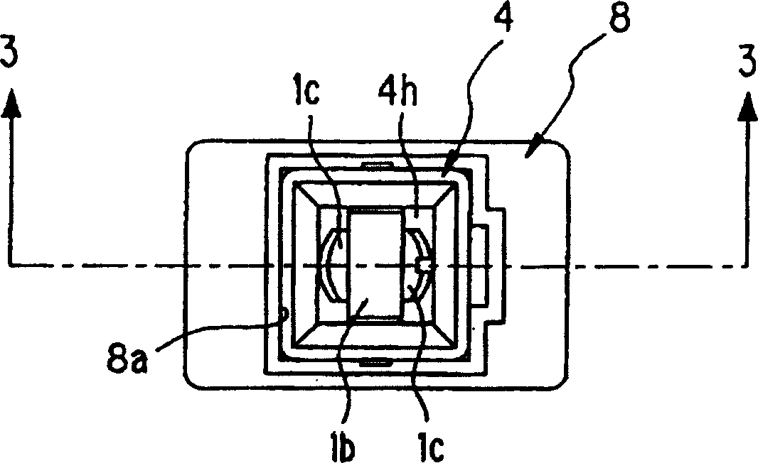
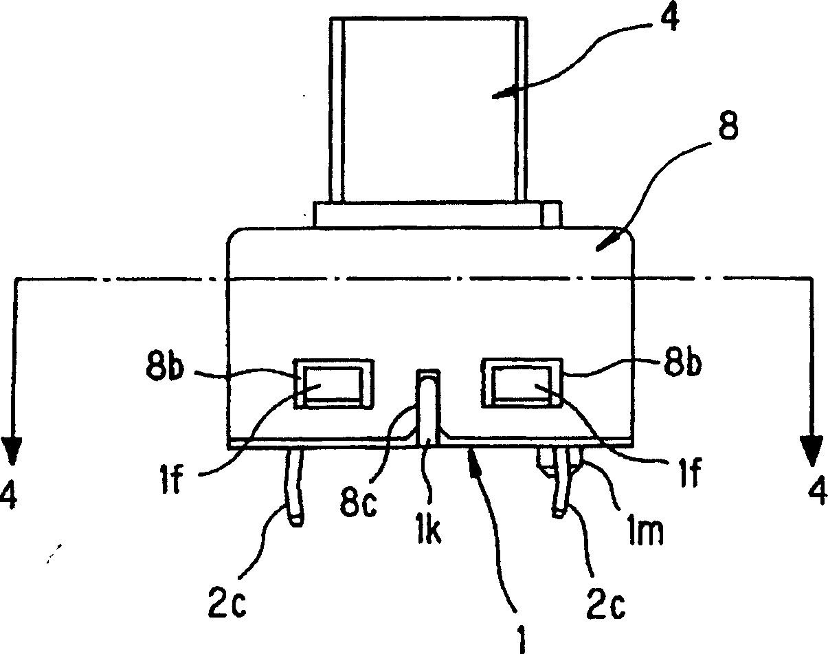
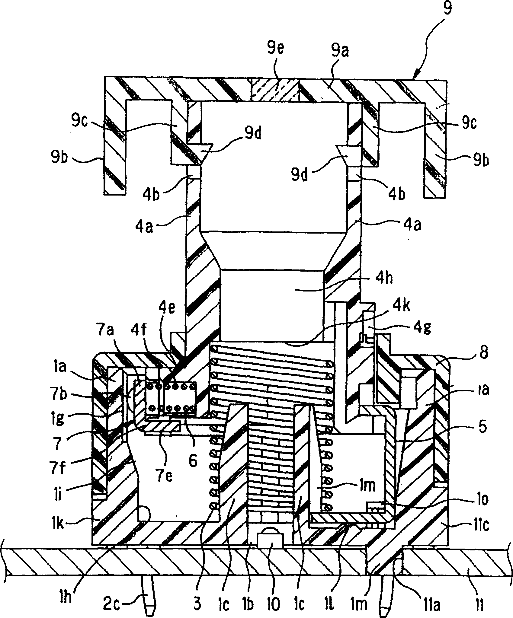
[0068] Embodiments of the present invention are described below with reference to the accompanying drawings, figure 1 It is a top view of the push button switch of the embodiment of the present invention, figure 2 yes figure 1 The front view of the pushbutton switch shown, image 3 is along figure 1 sectional view of the 3-3 line, Figure 4 is along figure 2 sectional view of line 4-4, Figure 5 6 is an exploded perspective view of the push button switch according to the embodiment of the present invention, and FIG. 7 is an exploded perspective view viewed from the back of FIG. 6 , Figure 8 It is a cross-sectional view showing a state in which the handle of the push button switch according to the embodiment of the present invention is pressed down.

[0069] Such as Figure 1 to Figure 8 As shown, the pu...


PUM


Abstract

In order to provide a miniature button switch which can arrange a display part near a light source by a simple structure and can illuminate the display part efficiently, the miniature button switch is provided with a casing which is pressed and operated and is provided with a through hole at the central part of the casing, the display part is formed at the top of the through hole, and the bottom surface of the casing is provided with an inserting hole which is opposite to the through hole; the miniature button switch is also provided with the light source which is contained inside the inserting hole and the through hole, and the through hole is linear along the pressing direction. Or in order to provide a button switch realizing miniaturization, the button switch is provided with the casing which is provided with a pair of fixed contacts which are parallel extended along the pressing operation direction, a movable contact component which is kept at an operating shaft, is elastically forced by an elastic component and is provided with movable contacts which are formed by a pair of protrudent parts which are elastically contacted with the fixed contacts respectively, and a contact separation guide part which is arranged at the casing and is contacted with a part between a pair of protrudent parts at a closing position along with the pressing operation to separate the movable contacts from the fixed contacts.

Description

technical field [0001] The present invention relates to a push button switch having an illumination structure for locking a power window or the like. [0002] In addition, the present invention also relates to a push button switch in which a fixed contact member is provided on the inner surface of a casing, and a movable contact member is provided on an operation shaft that can be contacted and separated from the fixed contact member. Background technique [0003] As a push button switch with an illumination structure, the structure of the first conventional example shown in Patent Document 1 is known, such as Figure 9 shown. [0004] As shown in this figure, the push button switch is made of the following parts: a button 21 with a light-transmitting display portion on the front; an escutcheon 23 of opaque material that is inserted into the button hole 22 of the button portion 21; A printed circuit board 25 of an opaque material with a switch 24 operated by the button 21 o...

Claims


Application Information

Patent Timeline
IPC IPC(8): H01H13/02
Inventor 森俊晴泽田谦次佐佐木敦实
Owner ALPS ALPINE CO LTD
Why Eureka
Try Eureka