
Relay

A relay, electrical signal technology, applied in relays, electromagnetic relays, electromagnetic relay details, etc., can solve problems such as temperature and pressure increase inside the shell, relay failure, etc.

Active Publication Date: 2006-01-04
TYCO ELECTRONICS AMP KOREA
View PDF0 Cites 4 Cited by
  • Summary
  • Abstract
  • Description
  • Claims
  • Application Information

AI Technical Summary

Problems solved by technology

This will cause the temperature and pressure inside the case to rise, causing the relay to malfunction

Method used


Image

  • Relay
  • Relay
  • Relay

Examples


Embodiment Construction

[0024] Now, preferred exemplary embodiments of the present invention will be described with reference to the accompanying drawings.

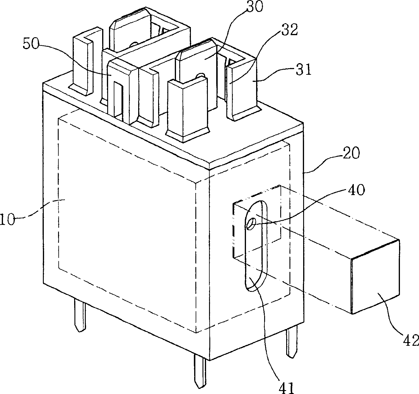
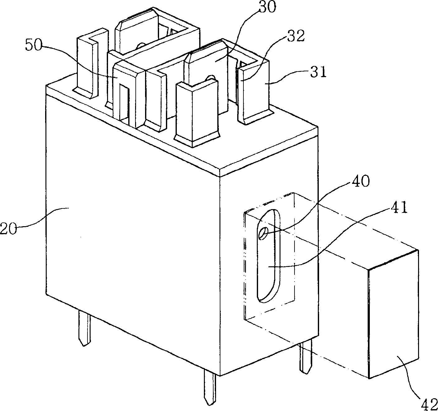
[0025] figure 1 is a perspective view of a relay with a separate cover according to an exemplary embodiment of the present invention, figure 2 is shown figure 1 A longitudinal section view of the important parts of the relay.

[0026] Such as figure 1 and 2 As shown, the relay according to the exemplary embodiment of the present invention includes a housing 20 accommodating the relay unit 10, and a plurality of external connectors 100 mounted on the top of the housing 20 for coupling the relay (see Figure 5 ) of terminal 30. The relay also includes a plurality of watertight enclosures 31 each surrounding a terminal 30 .

[0027] The terminal 30 is electrically connected with the relay unit 10 to provide electric energy or an operation signal to the relay unit 10 . These terminals 30 are composed of conductors, and are electrically co...


PUM


Abstract

The invention discloses a relay which can realize firmer coupling between a connector and a relay terminal and prevent damp from intruding into the terminal. The relay comprises a crust containing a relay unit which can trigger a switch to work according to an electric signal, and the relay also comprises one or a plurality of terminals which are provided at one side of the crust and are connected with the connector and a waterproof cover which is arranged as surrounding each terminal. By such a structure, the coupling between the connector and the relay can be firm and continuously kept stable under the influence of the vibration caused by the working process of various kinds of mechanical equipments or an electronic product comprising the relay or the outside impact. Therefore, the present invention can ensure that the relay works stably and continuously and prevent the electric accident caused by the power leakage of the relay.

Description

technical field [0001] The present invention relates to relays, and more particularly to relays capable of allowing a connector to be securely coupled to its terminals while preventing the ingress of moisture to the terminals. Background technique [0002] As we all know, a relay is a switch that cuts or connects a circuit by responding to an electrical signal, and is widely used in vehicles, various mechanical equipment and electronic products, etc. [0003] Figure 6 An example of a prior art relay is shown. The shown prior art relay is denoted by reference numeral 200, which includes a housing 201 to prevent the intrusion of dust and moisture, and a relay unit accommodated in the housing 201, the relay unit can trigger a switch to work according to an electrical signal . A plurality of contacts 202 are mounted on the top of the housing 201 for coupling the connectors. [0004] However, in the prior art relay 200, since the terminal protruding upward from the top of the...

Claims


Application Information

Patent Timeline
Patent Type & Authority Applications(China)
IPC IPC(8): H01H50/14H01H50/02H01R13/627
CPCH01H45/04H01H45/14
Inventor 李喆燮姜秉煜赵炳熙
Owner TYCO ELECTRONICS AMP KOREA
Learn More