Optical transmitter module

a technology of optical transmitter and module, which is applied in the direction of instruments, semiconductor lasers, optical elements, etc., can solve the problems of difficult to reduce the height of the optical transmitter module, the heat generated by the semiconductor laser element cannot be efficiently removed, and the semiconductor laser element cannot provide any stable laser transmission, so as to facilitate the joining of the optical isolator

Inactive Publication Date: 2005-08-16
OCLARO JAPAN INC
View PDF13 Cites 17 Cited by
  • Summary
  • Abstract
  • Description
  • Claims
  • Application Information

AI Technical Summary

Benefits of technology

[0013]Therefore, alignment for maximum light output can be accomplished by first bonding the end of the optical fiber to the top surface of the substrate member, thereby maki

Problems solved by technology

According to the above-mentioned related arts, the optical transmitter module described in JP-A-11-295560 has the disadvantages that the heat capacity of an object which is subject to temperature control through the Peltier cooler may be increased, so that the heat generated by the semiconductor laser element cannot be efficiently removed and the semiconduct

Method used


Image

  • Optical transmitter module
  • Optical transmitter module
  • Optical transmitter module

Examples


Embodiment Construction

[0020]Now, the embodiments of the present invention will be described below in detail with reference to FIGS. 1 through 4. In the drawings, some parts or bonding / fixation members are appropriately omitted to avoid any complexity of the drawings.

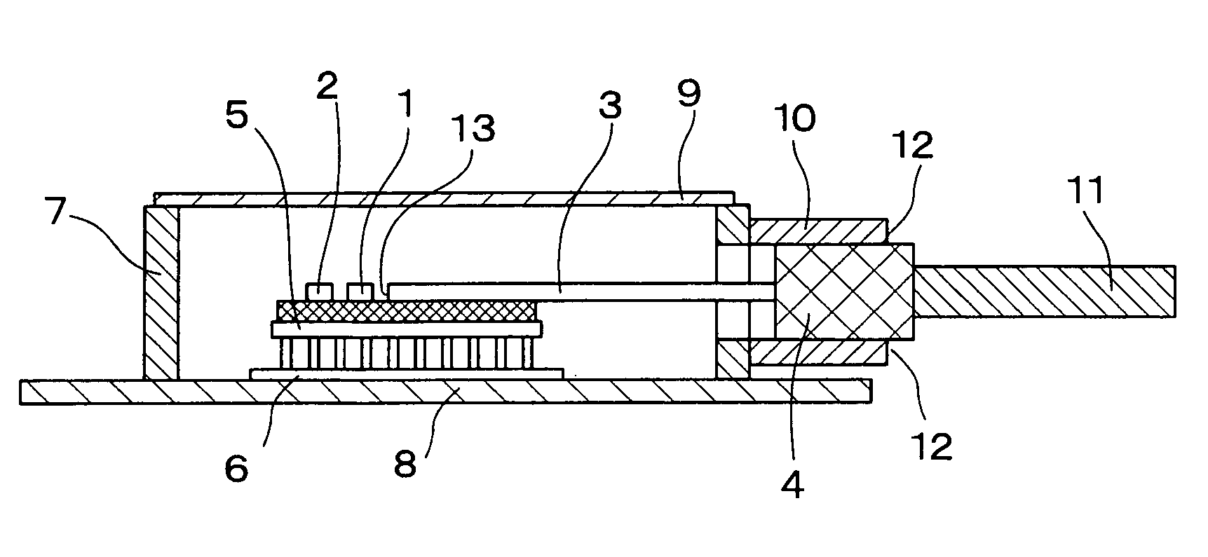
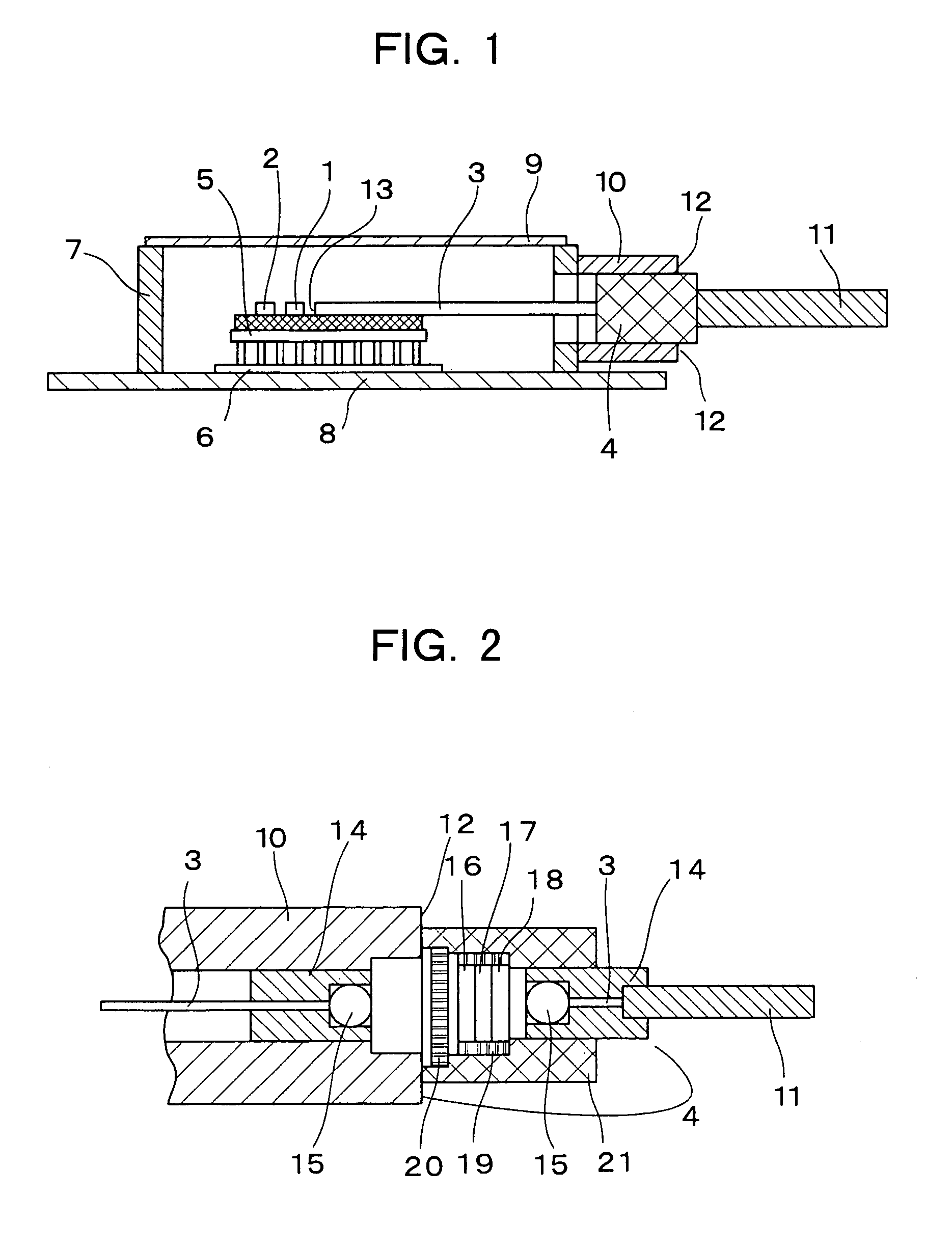
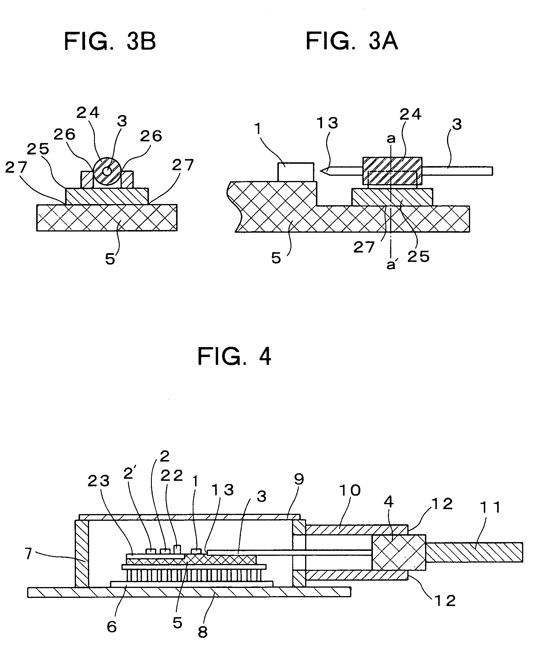
[0021]FIG. 1 shows a longitudinal sectional view of an optical transmitter module according to an embodiment of the present invention and the optical transmitter module has a laser diode 1 serving as a semiconductor light emitting element, a monitor photodiode 2 serving as a semiconductor light receptor element, a stem substrate (substrate member) 5 on which these semiconductor light emitting / receptor elements 1, 2 are mounted, a Peltier cooler 6 serving as a thermoelectric cooler with the stem substrate 5 mounted on the top surface thereof, an optical fiber 3 optically coupled to the laser diode 1 and the photodiode 2 for internally transmitting a laser light, and an inline optical isolator 4 provided between the optical fibers 3.

[0022]The s...


PUM


Abstract

A smaller and higher performance optical transmitter module is provided, which can improve the reliability and which can be manufactured at lower costs and allow for stable laser transmission of an optical semiconductor element. The optical transmitter module which has an optical semiconductor element, an optical fiber optically coupled to the optical semiconductor element, an inline optical isolator provided for the optical fiber, and a package case containing the optical semiconductor element and the optical fiber, includes a substrate member with one end of the optical fiber on the light incident side fixed thereon to be optically coupled to the optical semiconductor element, a thermoelectric cooler with the substrate member joined to the top surface thereof, and a pipe-like support member projecting from the side face of the package case for fixing the optical isolator.

Description

BACKGROUND OF THE INVENTION[0001]The present invention relates to an optical transmitter module for use in optical fiber transmission systems which transmit optical signals, and in particular, to an optical transmitter module which optically couples an optical semiconductor element to an optical fiber.RELATED ART[0002]Conventionally, in order to control the temperature of a semiconductor laser element from outside of the package and to miniaturize the optical transmitter module, it has been well known that the semiconductor laser element (optical semiconductor element) and an optical fiber are mounted and fixed on a base provided on a Peltier cooler (thermoelectric cooler) so that they are optically coupled to each other, that an optical branching device which divides input / output signal lights from the optical fiber to a receiving light receptor element is inserted in the middle of the optical fiber, and that a small inline isolator is further provided between the semiconductor las...

Claims


Application Information

Patent Timeline
IPC IPC(8): G02B6/42G02B6/26G02B27/28H01S5/022H01S5/024
CPCG02B6/4208G02B6/2746G02B6/4237G02B6/4238G02B6/4248
Inventor FUKUDA, KAZUYUKIKUWANO, HIDEYUKIFUJIWARA, YOSHITAKASHIMAOKA, MAKOTO
Owner OCLARO JAPAN INC
Why Eureka
Try Eureka