Soldering structure for mounting connector on flexible circuit board

a flexible circuit board and connector technology, applied in the direction of printed circuits, line/current collector details, electrical equipment, etc., can solve the problems of poor impedance control, easy damage to the electrical connection of the smd contact, poor flexibility of pin arrangement, etc., to achieve simple bonding structure, enhance bonding strength, and improve the effect of flexibility

Active Publication Date: 2014-05-29
ADVANCED FLEXIBLE CIRCUITS
View PDF9 Cites 14 Cited by
  • Summary
  • Abstract
  • Description
  • Claims
  • Application Information

AI Technical Summary

Benefits of technology

[0013]In another preferred embodiment of the present invention, each of solder-dipping pin holes formed in the flexible circuit board has an inner circumferential surface on which a first conductive layer and an extended portion are formed. Each of through holes of the reinforcement plate has an inner circumferential surface on which a second conductive layer and an extended portion are formed. With the flexible circuit board and the reinforcement plate bonded with an adhesive material layer, the extended portion of the first conductive layer and the extended portion of the second conductive layer form therebetween a solder filling gap, whereby a solder material is allowed to flow along the solder-dipping pin of the connector and the through hole of the reinforcement plate to fill into the solder filling gap so that electrical connection can be firmly established between the first conductive layer of the solder-dipping pin hole of the flexible circuit board and the second conductive layer of the through hole of the reinforcement plate.
[0014]In a further preferred embodiment o

Problems solved by technology

Such a component, such as a connector and an electronic device, may be detached from the flexible circuit board or the electrical connection of the SMD contact may get damaged due to frequent removals and insertions made by users.
In the transmission of high frequency differential mode signals, it is often overlooked of the importance of impedance control and mistakes and distortions of t

Method used


Image

  • Soldering structure for mounting connector on flexible circuit board
  • Soldering structure for mounting connector on flexible circuit board
  • Soldering structure for mounting connector on flexible circuit board

Examples


first embodiment

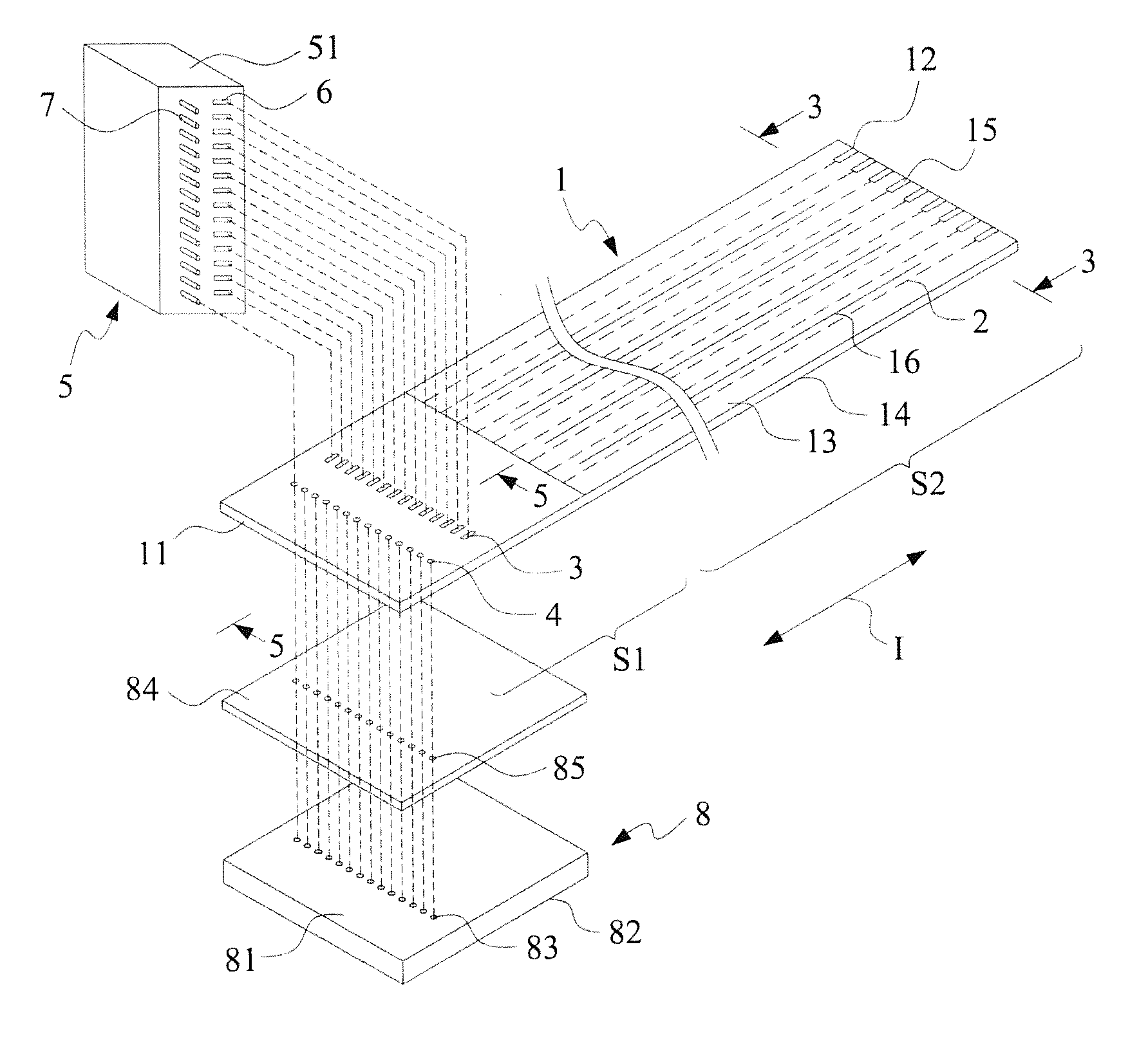
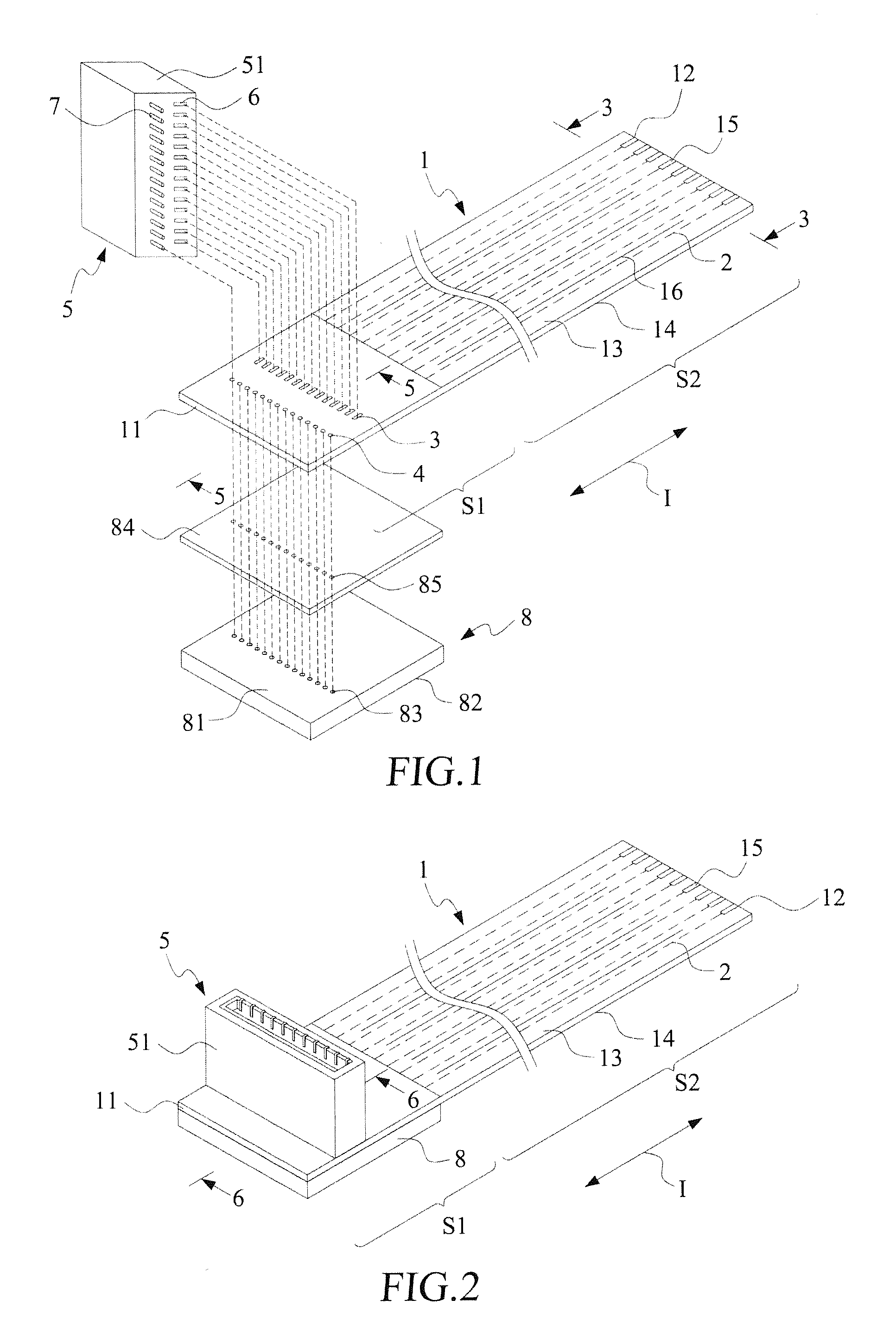
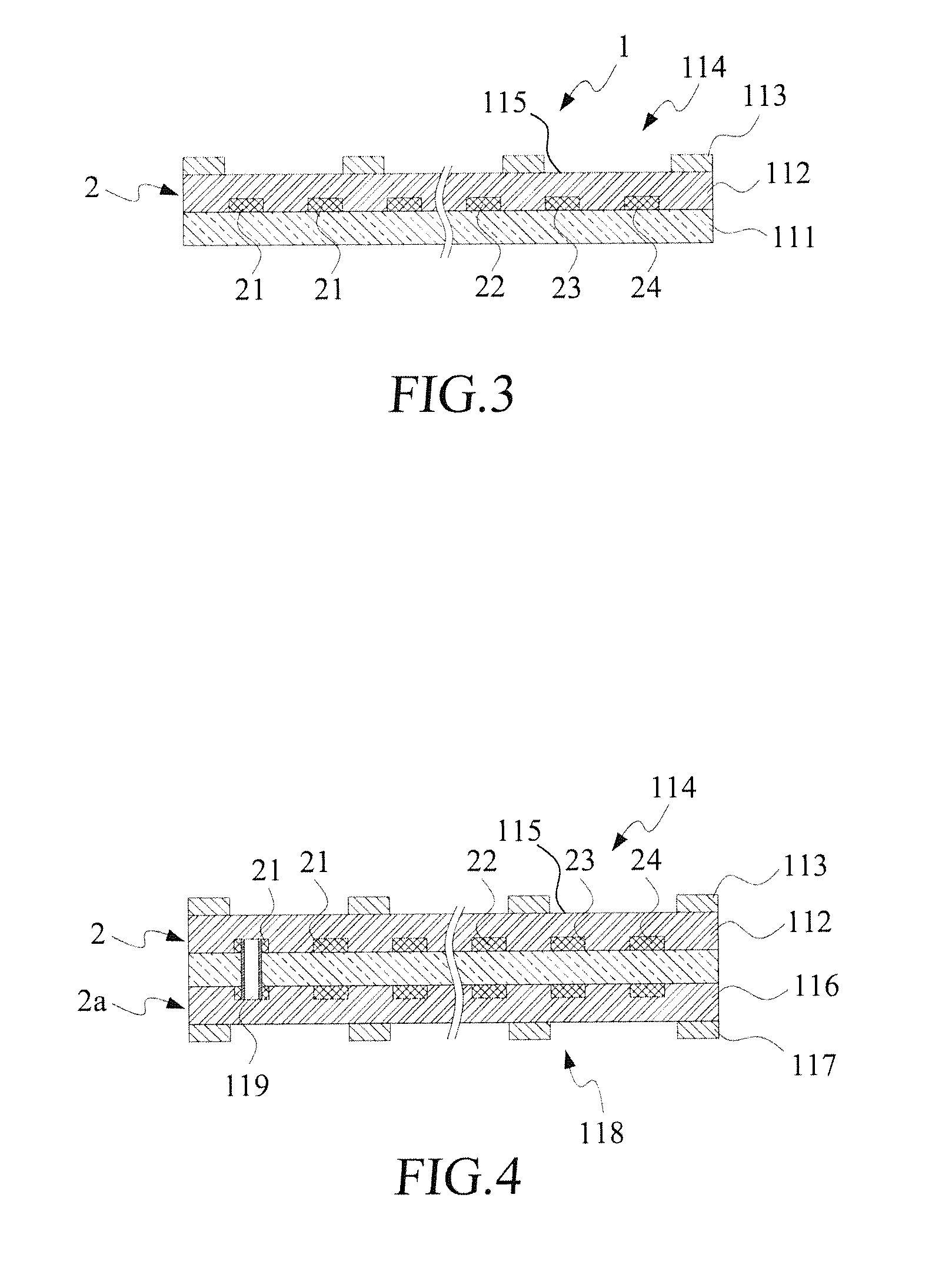
[0039]With reference to the drawings and in particular to FIGS. 1 and 2, a flexible circuit board 1 according to the present invention comprises a first end 11 and a second end 12, and a connector mounting section S1 formed adjacent to the first end 11 of the flexible circuit board 1. A first extension section S2 is formed and extends in an extension direction I between the first end 11 and the second end 12. The first extension section S2 comprises a plurality of conductor lines 2. The flexible circuit board 1 comprises a component surface 13 and a reinforcement bonding surface 14. The component surface 13 is provided with a plurality of SMD soldering zones 3 and is also provided with a plurality of solder-dipping pin holes 4 at locations close to the SMD soldering zones 3.

[0040]The second end 12 of the flexible circuit board 1 forms a golden finger insertion structure 15 that is known. The connector mounting section S1 of the first end 11 of the flexible circuit board 1 is coupled...

second embodiment

[0055]Referring to FIG. 9, the present invention is shown, where the flexible circuit board 1 and the reinforcement plate 8 further comprise at least one jumper via hole 87 extending through the flexible circuit board 1 and the reinforcement plate 8. The jumper via hole 87 comprises a conductive material 88 therein. The soldering surface 82 of the reinforcement plate 8 further comprises at least one conductive path 89 in connection with the jumper via hole 87 and having ends connected to one of the through holes 83 of the reinforcement plate 8 and the jumper via hole 87, whereby the solder-dipping pins 7 of the connector 5 can be connected to a grounding line G or other signal lines or a power line of the component surface 13 of the flexible circuit board 1 via the through holes 83 of the reinforcement plate 8, the conductive path 89, and the conductive material 88 inside the jumper via hole 87.

[0056]Referring to FIG. 10, a bottom view of an embodiment in which the soldering surface...

third embodiment

[0061]For example, as shown in FIG. 17, a pin-extended connector 5a according to the present invention comprises an array of SMD pins 6, an array of solder-dipping pins 7, and at least one array of extended solder-dipping pins 7a. To mate the pin-extended connector 5a, the component surface 13 of the flexible circuit board 1 is provided with an array of SMD soldering zones 3, an array of solder-dipping pin holes 4, and at least one array of extended solder-dipping pin holes 4a.

[0062]FIG. 18 is a cross-sectional view showing the pin-extended connector 5a of FIG. 17 is coupled to the component surface 13 of the flexible circuit board 1. In the instant embodiment, the array of solder-dipping pins 7 of the pin-extended connector 5a is inserted through the solder-dipping pin holes 4 of the flexible circuit board 1, the holes 85 of the adhesive material layer 84, and the through holes 83 of the reinforcement plate 8 to the soldering surface 82 of the reinforcement plate 8 and is then sol...


PUM


Abstract

Disclosed is a soldering structure for mounting at least one connector on a flexible circuit board. The connector includes SMD pins and solder-dipping pins. The flexible circuit board has a connector mounting section having a component surface on which SMD soldering zones and solder-dipping pin holes are formed. A reinforcement plate is coupled to a reinforcement bonding surface of the flexible circuit board. The reinforcement plate has through holes corresponding to the solder-dipping pin holes of the flexible circuit board. The SMD pins of the connector are respectively soldered to the SMD soldering zones of the flexible circuit board, and the solder-dipping pins of the connector are respectively inserted through the solder-dipping pin holes of the flexible circuit board and the through holes of the reinforcement plate to the soldering surface of the reinforcement plate to be soldered with a solder material.

Description

BACKGROUND OF THE INVENTION[0001]1. Field of the Invention[0002]The present invention relates to a mounting structure of a flexible circuit board and a connector, and in particular to a mounting structure that comprises a reinforcement plate coupled to a flexible circuit board.[0003]2. The Related Arts[0004]Printed circuit boards often possess the high strength nature of regular circuit board substrates so that they suffer hardly any problem in making connection with electronic component, insertion components, and insertion sockets provided in electronic devices. However, for the miniaturized, compact, and light-weighted electronic products that are prevailing in the present time, the conventional printed circuit boards do not suit the desired applications and are substituted by flexible circuit boards. Particularly, in electronic devices (such as mobile phones and cameras), where flexible manipulation, rotatable manipulation, and slidable manipulation may be desired, connections be...

Claims


Application Information

Patent Timeline
IPC IPC(8): H01R12/59
CPCH01R12/59H01R12/592H01R43/0256
Inventor LIN, GWUN-JINSU, KUO-FUCHUO, CHIH-HENG
Owner ADVANCED FLEXIBLE CIRCUITS
Why Eureka
Try Eureka